INSTALLATION & OPERATION MANUAL Digital Video Recorder DVR-3704T Before trying to connect or operate this product, please read this manual completely
SAFETY PRECAUTIONS All the following safety and operation instructions for the prevention of harm or damage to the operator or other persons should be read before the unit is operated. WARNING To reduce the risk of fire or electric shock, do not expose this appliance to rain or moisture. Do not block ventilation openings. Do not place anything on top of the unit that might spill or fall into it.
Table Of Contents 1. PRODUCT FEATURES .................................................................................................. 4 1.1 PRODUCT INTRODUCTION ...................................................................................................4 1.2 PRODUCT FEATURES .............................................................................................................4 2. DESCRIPTION OF THE FRONT/REAR VIEW............................................................... 6 2.
.5.5 SCHEDULE SETTING ................................................................................................................................. 26 5.6 DISK SETUP............................................................................................................................27 5.7 SYSTEM SETTING...................................................................................................................28 6. DISPLAY MODE ..............................................................
1. PRODUCT FEATURES 1.1 PRODUCT INTRODUCTION The DVR-3704 is a unique low-cost, high-performance digital video recorder supporting a 4-channel video input, 4 alarm inputs and one alarm output. It records at a real time speed, and displays video at the same speed rate per channel. Our device is capable of simultaneous triplex recording, playback and live modes, and provides a multi-screen on which to view your recorded images.
Easy field firmware update via USB device can be performed by the end user. Built-in USB connector to save image(s) for an individual channel to an USB device. 4 BNC video input channels. 4 alarm inputs and 1 alarm output. Audio recording. Quick setup menu. Disk-full warning. Supports factory default menu setting. Supports Play/Reverse-Play/Pause/Stop/FF/REW for playback.
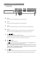
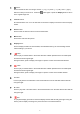
2. DESCRIPTION OF THE FRONT/REAR VIEW 2.1 FRONT VIEW 4CH DIGITAL VIDEO RECORDER 1 < button: Press to move the focus to desired items in the menu setup mode. 2 > button: Press to move the focus to desired items in the menu setup mode. 3 ^ button: Press to move within a desired option or value in the setup mode in the upward direction. 4 v button: Press to move within a desired option or value in the setup mode in the downward direction.
8 button: Press to double the size of an image. Use the "^" ( up ), "V" ( down ) , "<" ( left ) and ">" ( right ) buttons to shift your zoom focus . Press the button again or press the Display button to return to the original image size. 9 channel buttons: All channel buttons from 1 to 4 are sited here. Press each to display its channel in the live and play modes. 10 Search button: Press to enter the search mode to access recorded video. 11 Menu button: Press this to enter the setup menu.
18 █ (Stop) button: Press to stop playing back a recorded video from a hard disk and the LED will emit green light. 19 button: Press to start recording video into a hard disk while in the live display mode and the LED will emit green light. Press again for at least 3 seconds to stop the recording. 20 POWER button: Press this button for at least 3 seconds to switch off. Press again to activate the device. 21 (disk) Indicator: The indicator shows the operation status of the unit’s hard-disk drives.
2.2 REAR VIEW 1 DC jack: The inlet connects to an external power supply. Connect with the 12 V DC TUV-approved Power Supply; or connect with the UL Listed Class 2 Power Supply or ITE power supply marked ‘LPS’ or its equivalent. 2 RS-232 Port: The RS-232 communication port functions as a connector to an external control device. Please refer to the RS-232 Connection for more details.
2.3 ALARM In/Out DISK FULL ALARM RESET ALARM OUT RECORD IN GROUND 5 4 9 3 8 2 7 1 6 ALARM1 IN ALARM4 IN ALARM2 IN ALARM3 IN THE ABOVE FIGURE IS A REAR VIEW. 1. GND: Ground Contact. 2. ALARM OUT (OUTPUT): This is an alarm-output trigger. Connect this to external devices such as buzzers or lights. ( 5V 0V(Active) ) 3. DISK FULL (OUTPUT): This is a disk-full output trigger. Connect this to external devices such as buzzers or lights. ( 5V 0V(Active) ) 4.
3. BASIC OPERATIONS This section shows you how to operate and manage the DVR. 3.1 RECORDING OPERATIONS 3.1.1 Manual Recording When the DVR is in the live display mode, take the following steps to start recording: (1) In live display, press the button to record video into a hard-disk drive with the corresponding programmed recording settings. At once the device will emit a “beeping” sound signal and the (2) Press the button will light up indicating the DVR is in the recording status.
3.1.3 Timer Recording Timer recording provides seven schedules in a weekly table. This way the DVR will start and stop recording according to the programmed schedule. Please take the following steps to program the scheduled recording. (1) Press the MENU button to enter the MAIN MENU. (2) Select the ADVANCED SETTING and press the Enter button to enter the ADVANCED SETTING page. (3) Select the SCHEDULE SETTING and press the Enter button to enter the SCHEDULE SETTING page. (Please refer to section 5.5.
3.2 PLAYBACK OPERATIONS This section shows you how to operate the fast and single-picture playback functions, and details how the unit is to playback a file in a different operation status. Please refer to the following paragraphs specifying the relevant details. When playing a file, the PLAY button will light up indicating that the DVR is in the playback status. During playback, press the CH1-CH4 buttons to view the corresponding channels.
3.3 BACKUP OPERATIONS Archive Single image Clips into a USB device: Please take the following steps to archive a critical image in a USB device. (1) Insert a USB device into the USB slot of the front unit. (2) Start playing back the recorded video. (3) Press the button to freeze the desired image. (4) Press the Save button to save the image. While saving the image, the icon will appear on the screen.
3.4 KEY LOCK OPERATIONS To activate the key lock function: Press the “v” button for at least 3 seconds to activate the key lock function. The device will emit a “beeping” sound signal and show the message of “KEY LOCK”. To deactivate the key lock function: Press the “v” button for at least 3 seconds to deactivate the key lock function. The device will emit a “beeping” sound signal and show the message of “KEY UNLOCK”. 3.
4. SEARCH MODE This section shows you how to access recorded video. 4.1 RECORD LIST Take the following steps to proceed with the record-list search function. (1) Press the Search button to enter the search mode. (2) Select RECORD LIST and press the Enter button to access the complete list of recorded video. (3) Highlight the specific recorded video you require and press the Enter button to display the selected video.
ALARM LIST SEARCH 1.RECORD LIST 2.ALARM LIST 3.TIME FILTER HDD:HDD1 START TIME 08/15/2006 09:03 08/14/2006 19:22 08/14/2006 09:30 08/13/2006 11:00 08/12/2006 15:00 08/12/2006 08:03 08/10/2006 07:30 08/09/2006 10:10 08/08/2006 09:10 08/07/2006 08:13 ENTER ENTER ENTER 0001/0120 EVENT MOTION MOTION MOTION MOTION MOTION MOTION MOTION MOTION MOTION MOTION CH CH1 CH1 CH1 CH2 CH1 CH3 CH1 CH1 CH4 CH1 ZOOM KEY: SWICTH HDD 4.
5. MENU MODE There are 7 functional items for setting operations in the setup menu system as shown below. The following sections will instruct you step by step to configure setting the operations, and will state each item’s purpose and options. You can also use the “^” (up) and “v” (down) buttons to select any of the items. Once inside the item’s system, the on-screen menu allows you to set up the key features of the unit.
5.1 QUICK SETTING This page enables you to rapidly install your desired setting. For more detailed changes, enter each item page. QUICK SETTING MAIN MENU 1.QUICK SETTING 2.DISPLAY OPTION 3.SEQUENCE SETTING 4.PICTURE ADJUST 5.ADVANCED SETTING 6.DISK SETUP 7.SYSTEM SETTING 1.TIME SETTING 2.DATE SETTING 3.CH1 TITLE CH2 TITLE CH3 TITLE CH4 TITLE 4.RECORD RATE 5.RECORD QUALITY 6.RESOLUTION 7.
5.2 DISPLAY OPTION This item enables you to fix the display labels on your screen. DISPLAY OPTION MAIN MENU 1.QUICK SETTING 2.DISPLAY OPTION 3.SEQUENCE SETTING 4.PICTURE ADJUST 5.ADVANCED SETTING 6.DISK SETUP 7.SYSTEM SETTING 1.TIME SETTING 2.DATE SETTING 3.DATE MODE 4.CH1 TITLE CH2 TITLE CH3 TITLE CH4 TITLE 5.TIME/DATE DISPLAY: 6.BOUNDARY ENTER ENTER ENTER ENTER ENTER ENTER ENTER 09:51:02 15/08/2006 DD/MM/YYYY [CAM 1 ] [CAM 2 ] [CAM 3 ] [CAM 4 ] TOP WHITE 1.
5.3 SEQUENCE SETTING This page enables you to set the dwell time for displays in each channel and the 4-windows ( ) mode at your own preference anywhere between 0 (no-show) and 90 seconds when you press the button. Note: The button only works in the Live and Record modes. MAIN MENU 1 QUICK SETTING 2 DISPLAY OPTION 3.SEQUENCE SETTING 4.PICTURE ADJUST 5.ADVANCED SETTING 6.DISK SETUP 7.SYSTEM SETTING SEQUENCE SETTING ENTER ENTER ENTER ENTER ENTER ENTER ENTER 1.CH1 2.CH2 3.CH3 4.CH4 5.
5.5 ADVANCED SETTING This page includes multiple special functions. MAIN MENU 1 QUICK SETTING 2 DISPLAY OPTION 3.SEQUENCE SETTING 4.PICTURE ADJUST 5.ADVANCED SETTING 6.DISK SETUP 7.SYSTEM SETTING ADVANCED SETTING ENTER ENTER ENTER ENTER ENTER ENTER ENTER 1.RECORD SETTING 2.ALARM SETTING 3.MOTION SETTING 4.NETWORK SETTING 5.SCHEDULE SETTING ENTER ENTER ENTER ENTER ENTER 5.5.
5. AUDIO: This item has 2 options: "ON" and "OFF" (disable). Note: When the recording rate is set under 5 F/S (the lower recording rate), the Audio function will be turn off (disabled) automatically. 5.5.2 ALARM SETTING This page enables you to set all the various alarm - related functions. The device will record as long as the alarm is activating. ADVANCED SETTING 1.RECORD SETTING 2.ALARM SETTING 3.MOTION SETTING 4.NETWORK SETTING 5.SCHEDULE SETTING ALARM SETTING ENTER ENTER ENTER ENTER ENTER 1.
5.5.3 MOTION SETTING Here you can set the motion detection area of each channel. MOTION SETTING ADVANCED SETTING 1.RECORD SETTING 2.ALARM SETTING 3.MOTION SETTING 4.NETWORK SETTING 5.SCHEDULE SETTING 1. 1. SENSITIVITY MOTION CHECKING CH1 1 HIGHEST 03 F CH2 1 HIGHEST 03 F CH3 1 HIGHEST 03 F CH4 1 HIGHEST 03 F 2. DETECT AREA CH1 ENTER CH2 ENTER CH3 ENTER CH4 ENTER ENTER ENTER ENTER ENTER ENTER SENSITIVITY: Control the sensitivity of the motion detection function.
The user needs to see the situation in each channel in order to set a detection zone within the 8W ×6H (48) area. The effective points are marked “ “ ” (red) and the ineffective points are marked ” (yellow). The user can use the manual mode to set the target area. Please press the “^”, “v”, “<” or “>” buttons to select the points, and use the Enter button to mark them one by one; or press the Save button to activate the whole points. 5.5.4 NETWORK SETTING ADVANCED SETTING 1.RECORD SETTING 2.
NOTE: When connecting to a network, each connected DVR must be assigned a unique IP, which must be in the same class type as your network address. IP addresses are written as four sets of numbers separated by periods; for example, 192.168.1.1 Therefore, if the connected network is identified as Class C, for example, the first three sets of numbers of the DVR IP address must be the same as in the network address.
5.6 DISK SETUP Enter the disk setup mode to select your desired setting. MAIN MENU DISK SETUP 1 QUICK SETTING 2 DISPLAY OPTION 3.SEQUENCE SETTING 4.PICTURE ADJUST 5.ADVANCED SETTING 6.DISK SETUP 7.SYSTEM SETTING 1.HDD REFORMAT ENTER ENTER ENTER ENTER ENTER ENTER ENTER USB DEVICE INFO: USB TOTAL SIZE USB USEFUL SIZE ENTER NO DETECT NO DETECT 1. HDD REFORMAT: This option allows you to clear out all the data in the HDD. After entering the item, a message of “FORMAT HDD?” will appear.
5.7 SYSTEM SETTING Enter the system setting mode to select your desired setting. MAIN MENU 1 QUICK SETTING 2 DISPLAY OPTION 3.SEQUENCE SETTING 4.PICTURE ADJUST 5.ADVANCED SETTING 6.DISK SETUP 7.SYSTEM SETTING SYSTEM SETTING ENTER ENTER ENTER ENTER ENTER ENTER ENTER 1.VIDEO SYSTEM 2.MENU PASSWORD 3.MENU PWD ENABLE 4.LOAD FACTORY SETTING 5.UPDATE FIRMWARE SYSTEM VERSION NTSC 9999 OFF ENTER ENTER 1.00 1. VIDEO SYSTEM: Select the NTSC or PAL formats. In the NTSC system, the time display type is MM/DD/YYYY.
6. DISPLAY MODE You can display the HDD information as shown on Figure 6A below at any time by pressing the Display button. The unit displays status on a monitor as shown next. Figure 6A HDD MODEL: Shows the models of HDD. PICTURE 08/23/2006 10:05:24 HDD MODEL HDD SIZE HDD USED HDD READ HDD STATUS REC LIST ALM LIST HDD SIZE: The capacity of the installed hard disks. HDD1 ST340015A 40G 61% 00% REC 005 0000 HDD REST/TOTAL TIME USB REST/TOTAL SIZE HDD2 HDD USED: Percentages of system recording.
7. NETWORK VIEWER: INTRODUCTION Please use our Network Viewer to connect the DVR. It supports your local PC simultaneously with the DVR backup data. See below for the chief features of this Network Viewer. The programs can be operated by a selected PC equipped with the following requirements: 1. Intel Pentium III 750MHz (at least). 2. 128 MB RAM 3. Windows 2000, XP or above. 4. 4 MB Video card capable of 24-bit true color display. 5. 160 MB free hard-disk space for software installation. 6.
Point to the Local Area Connection and press the right mouse button. Click Properties to enter the Local Area Connection. 3. Click the Configuration tag; check if the TCP/IC is included in the network components list. If the TCP/IP is included, please process step 5. If it is not included, please follow step 4 to install the TCP/IP. 4. TCP/IP installation. During the installation, you will be requested to insert the windows XP CD ROM. After installation, the PC will be restarted.
5. TCP/IP Configuration setting Click Start Control Panel Network.Connections Local Area Connection Select Internet Protocol (TCP/IP), and then click Properties. Before processing the DVR installation in a WAN, please make sure the Internet connection works properly. If not, please contact your ISP provider. If you are using a DHCP server, please select “Obtain an IP address automatically”. Any assigned IP address for the connected DVRs must be in the same class type as the server.
7.2 CONNECTION TESTING As with the previous settings, follow the instructions below to ensure you have established the connection successfully. 1. Click Start Command Programs 2. Type in ping 192.168.1.1, then Enter. (See the sample screen below.) ** This IP is the DVR IP address that is assigned for the connected DVR. 3.If you receive a response as in the sample screen below, the connection hasn’t been successfully established.
7.3 SOFTWARE INSTALLATION Step 1: Exit all applications currently running in the selected PC. Step 2: Insert the supported PC in the CD-ROM device. It'll automatically enter the "Network Viewer" installation screen. Please see the screen below. Note: Please choose the "Next" button to continue. Step 3: The installation screen will show the message "C :\ Program Files \ Network Viewer\" Or you can select the path you want. Note: Click "Next" to continue the installation.
Step 4: The installation screen will show the message "Network viewer". Or you can enter the folder name you want. Note: Click "Next" to continue the installation. Step 5: Tick to create a desktop icon. Note: Click "Next" to continue the installation.
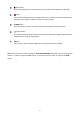
Step 6: Confirm the installation details. Note: Click "Install" to continue the installation. Step 7: The window below tells you the process is complete. Note: Click the "Finish" button to complete the installation process. Step 8: After completing installation, you can double-click the file shown below. Or click the "Start Menu" in the computer and select "Programs" to open the "Network Viewer" page. Then click the "Network Viewer" tag to start the program.
7.4 VIEW THE DVR VIDEO FROM A REMOTE PC Follow the instructions below to use the Network Viewer software to browse the DVR-3074 video from a remote location. Note: Every DVR provides only one user to login at one time. Upon entering the Network Viewer, a connection box will appear as follows. The default multi-screen is the 16-channel mode. Step 1: Press the button to enter the Network Viewer Setting window which is shown below.
Step 4: Press the button to enter the Network Viewer Setting window which is shown below. Step 5: Please type or select the IP address which is set in Step 2 from the drop-down list. Enter the password (the default is “9999”), then click the OK button. Step 6: After entering the DVR, you will see the videos of all the cameras as shown below. Note: To add more connections of other DVRs, please repeat the above instructions.
7.5 OPERATION Connect to a DVR: Press the button to enter the 1. Network Viewer Setting window. Select the IP address from the drop-down list which you want to connect, type the correct password, and then press the OK button to connect. 2. Open the local files: Press the button to open the recorded files in the disks. Note: Select the recorded file (*.dvr), and then press the 39 button to play it.
Set the working environment: (1) Type a new IP address. The Network Viewer can memorize 25 IP addresses of DVRs. Press the button to delete the IP information. (2) Enter the values of the ports. Please make sure the values of Data and Command ports 3. which you enter are the same as given in the NETWORK SETTING page of the DVR. (3) Select the recoding path you want for backup file. Press the button to select the recording path.
Pop-menu: You can use the mouse to move to each channel. Click the right key of the mouse to show a window. You can select Save "CamNo XX" Image, "Save All", Print "CamNo XX" Image, Reset "CamNo XX" Channel or "Reset All". Save single-channel image: Click to save a JPG image of the chosen channel. You can set the backup file path and the file name. 10. Save all images: Click to save four JPG images of 4 channels. You can set the backup file path and the file name.
8. SPECIFICATIONS Model Image System Video Resolution DVR-3704T NTSC PAL 720x240 pixels 720x288 pixels 360x240 pixels 360x288 pixels Operation Mode Triplex (Simultaneous Live, Play, Record and Network) Video Input BNC x 4 (termination: DIP SW) Video Output Main (BNC), Looping(BNC) x 4 Audio In/Out Audio Input x 1 (RCA) / Audio Output x 1 (RCA) Compression MJPEG Storage Media >750Gb / 1 Fixed HDD Archive USB Disk Watermark Embedded Digital Signature Recording Rate Max.
APPENDIX 1. – Insert the mobile rack To add the second hard disk into the DVR, the user has to insert the mobile rack first. To install the mobile rack, please take the following steps: Step 1: Loosen the mounting screw “ 1 “ in the mobile rack “Ⅰ“ of the DVR and detach it. Step 2: Draw out the mobile rack “Ⅰ“ from the DVR. Step 3: Insert the mobile rack “Ⅱ“ in the device and screw in screw “ 2 ”. Ⅰ Ⅱ Step 4: Insert the mobile rack “Ⅰ“ back in the device and screw in screw “ 1 “.
APPENDIX 2. – RS-232 Connection CONNECTION The transmission protocol is 8 data bit: 1 start bit, 1 stop bit and no parity. Five different speeds can be used: 1200 baud per second, 2400 baud, 4800 baud, 9600 baud and 19200 baud. The default setting is 2400 baud per second.
APPENDIX 3. – Compatible SATA hard-disk drives The compatible hard-disk drives, which can be used with the unit, are shown in the tables below.