
Owner manual

GP-XFP-1L-A
XFP, 10GBASE-LR 10G Ethernet Module
1310nm, 10km, SMF, LC RoHS6
_______________________________________________________
Approved Optics, Inc. www.ApprovedOptics.com
Page 4 of 5
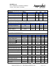
Parameter Symbol Min Typ Max Units
Bit Rate BR 9.95
11.1 Gb/s
Bit Error Ratio BER
10-12
Max. Supported Link Length LMAX 10
km
MTBF HRS 715,000
hrs
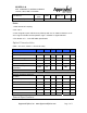
Digital Diagnostic Functions
GP-XFP-1L-A 10Gb/s (XFP) transceivers are compliant with the current XFP Multi-
Source Agreement (MSA) Specification Rev 4.5.
As defined by the XFP MSA, XFP transceivers provide digital diagnostic
functions via a 2-wire serial interface, which allows real-time access to the following
operating parameters:
• Transceiver temperature
• Laser bias current
• Transmitted optical power
• Received optical power
• Transceiver supply voltage
It also provides a sophisticated system of alarm and warning flags, which may be
used to alert end-users when particular operating parameters are outside of a factory-
set normal range.
The operating and diagnostics information is monitored and reported by a Digital
Diagnostics Transceiver Controller inside the transceiver, which is accessed through
the 2-wire serial interface. When the serial protocol is activated, the serial clock
signal (SCL pin) is generated by the host. The positive edge clocks data into the
XFP transceiver into those segments of its memory map that is not write-protected.
The negative edge clocks data from the XFP transceiver. The serial data signal (SDA
pin) is bi-directional for serial data transfer. The host uses SDA in conjunction with
SCL to mark the start and end of serial protocol activation. The memories are
organized as a series of 8-bit data words that can be addressed individually or
sequentially. The 2-wire serial interface provides sequential or random access to the 8
bit parameters, addressed from 000h to the maximum address of the memory.