6000 Series Zone Control System For models 6010, 6015, 6020, 6025, 6030, 6035, 6040, 6045, 6045M Safety & Installation Instructions SAFETY INSTRUCTIONS Read this entire installation manual before beginning installation of the Aprilaire 6000 Series Zone Control System. For questions call Aprilaire customer support at (800) 334-6011 or visit AprilairePartners.com. WARNING 1. 120 volts may cause serious injury from electrical shock. Leave power disconnected until installation is complete. 2.
TABLE OF CONTENTS SAFETY INSTRUCTIONS ������������������������������������������������������������������������������������������������������������������������������������������������������������������������������������������������������������������������������������ 1 SPECIFICATIONS �����������������������������������������������������������������������������������������������������������������������������������������������������������������������������������������������������������������������������������
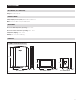
SPECIFICATIONS INPUT RATINGS (6000 SERIES HUB) Voltage: 18-30VAC 50/60 Hz MAXIMUM CURRENT Damper output per zone (fused): 18VA at 158°F, 30VA at 90°F Note: Use 18 or 20 AWG solid (non-stranded) wire ENVIRONMENT 6000 Series Hub Temperature (operating): 32°F – 158°F 6000 Series Control and Sensors (operating): 32°F – 120°F Temperature (shipping): -30°F – 150°F Humidity: 5% – 90%, non-condensing DIMENSIONS FIGURE 1 – DIMENSIONS IN INCHES (mm) 11.19 (284) 4.99 (127) 4.38 (111) 8.
APPLICATIONS The Aprilaire 6000 Series Zone Control System is available in these configurations: Model 6010 2 Zone Hub Black Control 1 Black Sensor Model 6030 2 Zone Hub Black Control Model 6015 2 Zone Hub White Control 1 White Sensor Model 6035 2 Zone Hub White Control Model 6020 3 Zone Hub Black Control 2 Black Sensors Model 6040 3 Zone Hub Black Control Model 6025 3 Zone Hub White Control 2 White Sensors Model 6045 3 Zone Hub White Control Model 6045M 3 Zone Hub White Contro
LAYOUT 6000 SERIES HUB TERMINALS 1. HVAC – HVAC connection. 2. JUMPER – RH/RC Jumper. 3. ZONE 1 CONTROL – 6000 Series Control connection. 2 4. ZONE 2 CONTROL – 6000 Series Sensor 2 connection. 3 5. ZONE 3 CONTROL – 6000 Series Sensor 3 connection (3 Zone models only). 6. DAMPER 1 – Zone 1 damper connection. 7. DAMPER 2 – Zone 2 damper connection. 1 8. DAMPER 3 – Zone 3 damper connection (3 Zone models only). 9. REMOTE SENSORS DAT (Discharge Air Temperature). 10.
000 SERIES CONTROL HOME SCREEN CURRENT DATE AND TIME (AUTOMATICALLY UPDATED IF CONNECTED TO INTERNET) WI-FI INDICATOR (STROBES IN SETUP MODE) HEAT SETTING COOL SETTING ZONE SELECTION ROOM TEMPERATURE & HUMIDITY CURRENT SCREEN RELATED HELP MAIN MENU HEATING AND COOLING EQUIPMENT STATUS HUMIDIFIER AND OR DEHUMIDIFIER INDOOR AIR QUALITY SCREEN & SIMPLE STATUS OUTDOOR TEMPERATURE AIR CLEANING INDOOR AIR QUALITY SCREEN & SIMPLE STATUS FAN MODE SELECTION FRESH AIR INDOOR AIR QUALITY SCREEN & SIMPLE S
6000 SERIES HUB INSTALLATION LOCATION 1. Mount the 6000 Series Hub near the HVAC equipment, on an interior wall, stud or return duct. See FIGURE 2. FIGURE 2 – 6000 SERIES HUB MOUNTING LOCATION 2. Locate the Discharge Air Temperature (DAT) in the supply trunk, downstream of the heat exchanger and cooling coils, and before the zone dampers (refer to the shaded areas of FIGURE 2).
6000 SERIES HUB WIRING WARNING FIGURE 5 – WIRE TIE MOUNTS 120 volts may cause serious injury from electrical shock. Sudden operation may cause serious injury from moving parts. Leave power disconnected until installation is complete. Follow these steps for all system connections. Wiring will vary depending on equipment. Wiring of the system must comply with applicable codes, ordinances and regulations. • Use only 18 or 20 gauge solid (non-stranded) wire.
DAMPER • Run 2-conductor thermostat wire for spring return dampers (normally open or normally closed). FIGURE 7 – NORMALLY OPEN / POWER CLOSE DAMPERS • Run 3-conductor thermostat wire for power open/power close dampers. • Multiple dampers for the same zone can be wired in parallel as shown in FIGURES 7 & 8. • Wire the dampers to the 6000 Series Hub: NC – This terminal is used to power open a normally closed damper. For power open and power close dampers this terminal is used to power open the damper.
OUTDOOR TEMPERATURE SENSOR (INCLUDED) • Wire the outdoor temperature sensor Model 8052 to the “ODT” terminals as shown. See FIGURE 10. FIGURE 10 – OUTDOOR TEMPERATURE SENSOR • Maximum distance of the ODT sensor from the 6000 Series is 300 feet. • Do not wire along 120VAC lines. • Outdoor temperature sensor should be mounted: MODEL 8052 TEMP SENSOR 90-2088 –– On side of building out of direct sunlight. –– Above snow line. –– At least 3 feet away from exhaust vents and condensing lines.
HVAC EQUIPMENT WIRING DIAGRAMS FIGURE 13 – TWO-STAGE FURNACE AND A/C FIGURE 14 – TWO-STAGE HEAT PUMP JUMPER INSTALLED JUMPER INSTALLED TWO STAGE HEAT PUMP RH R RC W W1 W W2 W2 W2 Y Y1 Y Y2 Y2 Y2 HVAC RC G G O O O B L B L C G L C 90-2417 C 90-2418 FIGURE 15 – BOILER AND A/C FIGURE 16 – RADIANT FLOOR FIRST-STAGE HEAT, FURNACE SECOND-STAGE HEAT AND A/C JUMPER INSTALLED JUMPER REMOVED BOILER AND A/C R RH BOILER C RC W W R RADIANT FLOOR C HEAT W1 W2 Y Y2 G HVAC R IN
INDOOR AIR QUALITY WIRING DIAGRAMS FIGURE 17 – INDOOR AIR QUALITY WIRING WITH SEPARATE TRANSFORMERS FIGURE 18 – INDOOR AIR QUALITY WIRING WITH A SINGLE TRANSFORMER HUMIDIFIER HUMIDIFIER TRANSFORMER DEHUMIDIFIER DEHUMIDIFIER NORMALLY CLOSED DAMPER NORMALLY CLOSED DAMPER TRANSFORMER TRANSFORMER Note: Outputs are 24VAC dry contact. Refer to individual product installation instructions for more details. 90-2425 12 Note: Outputs are 24VAC dry contact.
6000 SERIES CONTROL AND SENSORS INSTALLATION LOCATION RECOMMENDATIONS 6000 Series Control and Sensors should be mounted: • On an interior wall, in a frequently occupied space. • Approximately 5 feet above floor. • At least 18" from outside wall. • Displays can be mounted to a vertical junction box. Do not mount: • Behind doors, in corners, or other dead air spaces. • In direct sunlight, near lighting fixtures, or other appliances that give off heat. • On an outside or unconditioned area wall.
WIRING WIRE SPECIFICATIONS: 18-24 gauge thermostat wire FIGURE 21 – 4-WIRE CONNECTION, 6000 SERIES CONTROL INSTALLATION NOTES: Control to Hub • Ensure power at the 6000 Series Hub is off. • Insert stripped wire (Hub). • Loosen screw terminals (Control), insert stripped wire and re-tighten. • Push the excess wire at Control, back into the opening and plug the wall opening to prevent drafts.
INSTALLER SETUP 6000 SERIES CONTROL The 6000 Series Hub is powered by 24VAC. The 6000 Series Control is powered by the 6000 Series Hub. In the case of power loss, the system will maintain the clock for 24 hours. The system has a memory backup that saves the system settings in case of power interruption. The factory reset is located in the Installer Tools option of the Installer Menu. See Installer System Settings section for details.
TABLE 4: THERMOSTAT SYSTEM SETTINGS Factory Default Settings (bold) and Settings Range System Setting Description Equipment Type Note: Equipment Type related settings will return to defaults if this is changed. Heat/Cool Heat Pump Control Setup Used to lockout heating or cooling outputs. (Heat/Cool mode only.) Heat & Cool Heat Only Cool Only Heat Pump Auxiliary Type Selects auxiliary type. (Heat Pump mode only.
TABLE 4: THERMOSTAT SYSTEM SETTINGS Factory Default Settings (bold) and Settings Range System Setting Description RH Sensor Offset Zone 1 Field adjustment of internal RH sensor. 0 -5 to 5 Temp Sensor Offset Zone 2 Field adjustment of controlling temperature sensors. 0°F (0°C) -4 to 4°F (-2 to +2°C) RH Sensor Offset Zone 2 Field adjustment of internal RH sensor. 0 -5 to 5 Temp Sensor Offset Zone 3 Field adjustment of controlling temperature sensors.
TABLE 5: ZONE SYSTEM SETTINGS Factory Default Settings (bold) and Settings Range System Setting Description Number of Zones Number of zones detected. 1 2 3 Staging Based On Staging based on Zones. Zone Number of Zones Zones to Stage Selects how many Zones are required to stage up. Note: Only option if ZONES is enabled. 2 1-9 Zone 1 Weighting The amount of precedence each zone has. 1 2 3 Zone 2 Weighting The amount of precedence each zone has.
INDOOR AIR QUALITY (IAQ) The following tables contain the Indoor Air Quality system settings and their details. Default settings are shown in bold. Some settings are only present dependent upon the value of other settings. The use of an outdoor temperature sensor (recommended) enables additional Indoor Air Quality functionality. Please refer to the Owner’s Manual for further information about control features.
TABLE 7: DEHUMIDIFIER SYSTEM SETTINGS Factory Default Settings (bold) and Settings Range System Setting Description Dehumidifier Type Installed? Selects whether a dehumidifier is installed. (If set to None, no other dehumidifier settings will be available.) None Whole Home Air Conditioner Overcooling Display Button? Note: Only available if Dehumidifier Installed is set to None Yes No Disable Dehumidification During Cooling? Selects whether a dehumidifier is disabled during a cooling call.
TABLE 9: FRESH AIR SYSTEM SETTINGS Factory Default Settings (bold) and Settings Range System Setting Description Fresh Air Vent Installed? Select whether ventilation is installed. (If set to No, no other ventilation settings will be available.) No Yes (6045M default is Yes) Display Button? Note: only available if Fresh Air Installed is set to No. Yes No Fresh Air Setup Type ASHRAE: hourly ventilation time will be calculated using the ASHRAE recommendations.
WI-FI SETUP The 6000 Series Zone Control System can be connected to a Wi-Fi network with the Aprilaire App, on the 6000 Series Control, or with another Wi-Fi device with a web browser. STEP 1: Verify the 6000 Series Control is in Wi-Fi Connection Mode. The 6000 Series Control by default will be in Wi-Fi Connection Mode. To confirm that the 6000 Series Control is in Wi-Fi Connection Mode, verify that the radio bars on 6000 Series Control are strobing as shown below.
6000 SERIES SENSOR ZONE NUMBER SELECTION When the 6000 Series Sensor is connected and powered for the first time it will display – and “select zone”, the installer will be prompted to select a zone number of 2 or 3. Pressing the up or down arrow will display 2 or 3. The 6000 Series Sensor will revert to Room Temperature Display 5 seconds after selecting a zone number. INSTALLER TEST There are two options for performing installer checkout test, from the 6000 Series Control or from the 6000 Series Hub.
TABLE 9: HEAT COOL INSTALLER SETTING HVAC Equipment Outputs Test Step Test Description Y Y2 W W2 O B G 1 Stage 1 Heat, Heat Cool OFF OFF ON OFF OFF ON ON 2 Stage 2 Heat, Heat Cool OFF OFF ON ON OFF ON ON 3 Stage 1 Cool ON OFF OFF OFF ON OFF ON 4 Stage 2 Cool ON ON OFF OFF ON OFF ON 5 Fan OFF OFF OFF OFF ON OFF ON Test Step Test Description HUM/AUX DEH VENT G 6 Humidifier ON OFF OFF ON 7 Dehumidifier OFF ON OFF ON 8 Ventilation OFF OF
SEQUENCE OF OPERATION The Aprilaire 6000 Series Zone Control System is a heat call priority system with automatic heating/cooling changeover after 20 minutes of operation. If two opposing (heating/cooling) thermostat calls exist while the system is idle, the heating call will be satisfied first. HEAT/COOL CHANGEOVER When a call for heating/cooling exists and an opposing call is made from another zone, a changeover time limit of 20 minutes begins at the time that the opposing call is made.
MULTISTAGE EQUIPMENT STAGING The 6000 Series Zone Control System can be configured to control staging of multi-stage HVAC equipment in two ways, based on the Staging Based On setting. STAGING BASED ON THE ZONE When Staging Based On is set to Zone, the 6000 Series Zone Control System will stage the HVAC equipment to the highest stage call.
TROUBLESHOOTING DISPLAY IS BLANK If Power LED is not illuminated at the 6000 Series Hub check the following: • Check circuit breaker and reset if necessary. • Make sure power switch at heating & cooling system is on. • Make sure furnace door is closed securely. HEATING SYSTEM DOES NOT RESPOND (“HEATING” APPEARS ON SCREEN) • Check for 24VAC at the equipment on the secondary side of the transformer between power and common.
LIMITED WARRANTY Your Research Products Corporation Aprilaire® 6000 Series Zone Control System® is expressly warranted for five (5) years from date of installation to be free from defects in materials or workmanship. Any modifications to the product voids the warranty.