Model 6404 & 6403 Zoned Comfort Control® Safety & Installation Instructions READ AND SAVE THESE INSTRUCTIONS 61001165A 6403-6404 Zoned Comfort Control Install.
TABLE OF CONTENTS SAFETY INSTRUCTIONS �������������������������������������������������������������������������������������2 SPECIFICATIONS �������������������������������������������������������������������������������������������������3 APPLICATION & ACCESSORIES �����������������������������������������������������������������������3 ZONE PANEL LAYOUT ���������������������������������������������������������������������������������������� 4 INSTALLATION �������������������������������������������������
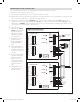
SPECIFICATIONS INPUT RATINGS FIGURE 1 – ZONE PANEL DIMENSIONS IN INCHES (mm) Voltage: 18-30VAC 50/60 Hz MAXIMUM CURRENT Damper output per zone (fused): 18VA at 158°F, 30VA at 90°F Zone panel and thermostats (fused): 18VA at 158°F, 30VA at 90°F Zone panel consumption: 4VA max Note: Use 18 or 20 AWG solid (non-stranded) wire 14.72 (374) ENVIRONMENT Temperature (operating): 32°F – 158°F Temperature (shipping): -40°F – 165°F Humidity: 5% – 90%, non-condensing DIMENSIONS 8.85 (225) See FIGURE 1. 90-2071 1.
ZONE PANEL LAYOUT TERMINALS LEDs 1. HVAC – HVAC connection 15. POWER – Green: 24VAC is present. Flashing: TDO button is pressed. 2. ZONE 1 THERMOSTAT – Thermostat connection 16. HEATING – Green: Heating is active. Flashing: DAT high temperature limit reached. 3. ZONE 2 THERMOSTAT – Thermostat connection 17. COOLING – Green: Cooling is active. Flashing: DAT low temperature limit reached. 4. ZONE 3 THERMOSTAT – Thermostat connection 5. ZONE 4 THERMOSTAT (6404 only) – Thermostat connection 18.
INSTALLATION MOUNTING 1. Separate the zone panel cover from the base. See FIGURE 3. FIGURE 3 FIGURE 4 – MOUNTING HOLE LOCATIONS 2. Use the base as a template to drill mounting holes. See FIGURE 4 for mounting hole locations. USE TWO SCREWS WHEN ATTACHING TO A WALL STUD USE FOUR SCREWS WHEN ATTACHING TO DRYWALL/PLASTER 3. Attach the base to an interior wall, stud or return duct. 2 1 90-2107 90-2072 INSTALLATION LOCATION RECOMMENDATIONS 1. Mount the zone panel near the HVAC equipment.
WIRING WARNING FIGURE 6 – WIRE TIE MOUNTS 120 volts may cause serious injury from electrical shock. Sudden operation may cause serious injury from moving parts. Leave power disconnected until installation is complete. Follow these steps for all system connections. Wiring will vary depending on equipment. See page 11 for complete wiring diagram examples. Wiring of the zone panel must comply with applicable codes, ordinances and regulations.
ZONE DAMPER WIRING • Run 2-conductor thermostat wire for spring return dampers (normally open or normally closed). FIGURE 9 – NORMALLY OPEN / POWER CLOSE DAMPERS • Run 3-conductor thermostat wire for power open/power close dampers. • Multiple dampers for the same zone can be wired in parallel as shown in FIGURES 9 & 10. • Wire the dampers to the zone panel: –– NC – This terminal is used to power open a normally closed damper.
DISCHARGE AIR TEMPERATURE SENSOR (INCLUDED) • Wire the discharge air temperature sensor Model 8052 to the “DAT” terminals as shown. See FIGURE 12. FIGURE 12 – DISCHARGE AIR TEMPERATURE SENSOR • Maximum distance of the sensor from the zone panel is 300 feet. • Do not wire along 120VAC lines. • Refer to FIGURE 5 on page 5 for the proper mounting location of the discharge air temperature sensor.
EXPANSION PANELS (OPTIONAL – MODEL 6404 ONLY) Up to four expansion panels, each with 2 zones, can be added to the zone panel if additional zones are required. To add Model 6401 expansion panels, follow these steps: 1. Disconnect the Power and Damper Power on the zone panel until installation is complete. 2. Mount the expansion panels using four #8 screws (supplied) in location where temperature will not exceed 158°F and will not drop below freezing 32°F.
THERMOSTAT TERMINAL DEFINITIONS R – 24VAC power to thermostat C – 24VAC power to thermostat W – First stage heat (conventional) / First stage auxiliary (heat pump) W2 – Second stage heat (conventional) / Second stage auxiliary (heat pump) Y – First stage cooling (conventional) / First stage compressor(heat pump) Y2 – Second stage cooling (conventional) / Second stage compressor (heat pump) G – Fan O – Reversing valve (heat pump) L – System fault indicator (heat pump) (optional) NOTE: The L output to the the
TWO-STAGE FURNACE AND A/C BOILER AND A/C HVAC TERMINAL DEFINITIONS HVAC TERMINAL DEFINITIONS Y1 – First stage cooling Y1 – First stage cooling Y2 – Second stage cooling W1 – First stage boiler heat W1 – First stage heating G – Fan W2 – Second stage heating G – Fan BOILER AND A/C R BOILER C W FIGURE 16 – TWO-STAGE FURNACE AND A/C JUMPER R W1 W2 Y1 Y2 G RH RC W W2 Y Y2 G O B L C INDOOR AIR R HANDLER Y1 AND A/C G HVAC FURNACE AND A/C RH RC W W2 Y Y2 G O B L C HVAC FIGURE 18 – BOILER AND A/C
INSTALLER SETUP HOW TO CONFIGURE • Press the BACK and NEXT buttons for 7 seconds continuously. • The message INSTALLER SETUP ENABLED will be displayed for 2 seconds and then transition to the first system setting. • Use the or arrows to adjust the setting. • The BACK button will accept the current setting and navigate to the previous system setting. • The NEXT button will accept the current setting and navigate to the next system setting unless the last system setting is displayed.
LCD INSTALLER SCREEN SETTINGS & DESCRIPTIONS TABLE 1 – INSTALLER SETUP Factory default setting (bold) and setting range Menu Title Description EQUIPMENT TYPE Selects if zone panel is controlling a Heat/Cool or Heat Pump system. HEAT/COOL HTPUMP COOLING STAGES Number of cooling stages. Note: Only displayed if EQUIPMENT TYPE is set to HEAT/COOL. 1 2 COMPRESSOR STAGES Number of compressor stages. Note: Only displayed if EQUIPMENT TYPE is set to HTPUMP. 1 2 HEATING STAGES Number of heating stages.
SEQUENCE OF OPERATION The 6404/6403 zone panel is a heat call priority system with automatic heating/cooling changeover after 20 minutes of operation. If two opposing (heating/cooling) thermostat calls exist while the system is idle, the heating call will be satisfied first. The zone panel can be configured to control either a conventional heat/cool system or heat pump system based on the EQUIPMENT TYPE setting.
COOLING OPERATION Staging Based on Zones Calling When a thermostat makes a call to the zone panel for cooling, The zone panel will initiate a cooling call to the equipment and close the damper for all zones that are not calling for cooling.
LCD HOME SCREEN DISPLAY & DESCRIPTIONS The LCD will display the zone panel status during normal operation. The table below shows the available messages and a corresponding description. TABLE 2 – LCD HOME SCREEN Message Type Display Context Message Text The outdoor temperature will be displayed if OUTDOOR SENSOR is set to YES. OUTDOOR SENSOR F The discharge air temperature will be displayed if DAT SENSOR is set to YES. DAT SENSOR F Vacation mode is enabled with the Vacation button.
INSTALLER CHECKOUT • The Installer checkout is entered by holding the and buttons for 7 seconds continuously. Upon entering the Installer checkout all outputs will turn off and thermostat inputs will be ignored. The SYSTEM CHECKOUT message will be displayed for 2 seconds and then transition to the first step of the installer checkout as shown in the diagram on this page.
LIMITED WARRANTY Your Research Products Corporation Aprilaire® Zoned Comfort Control® is expressly warranted for five (5) years from date of installation to be free from defects in materials or workmanship.
61001165A 6403-6404 Zoned Comfort Control Install.
AprilairePartners.com P.O. Box 1467 Madison, WI 53701-1467 800-334-6011 F: 608-257-4357 61001165A 6403-6404 Zoned Comfort Control Install.indd 20 ©2015 Aprilaire – A division of Research Products Corporation 61001165 B2206566A 11.