
Install Instructions
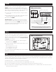

TROUBLESHOOTING
M
RED
BLOWER
RUN CAPACITOR
GRN
BLU
BRN
BRN
BLK
WHT
CONNECTOR
BLK
GRN
L2-WHT
L1-BLK
CHASSIS
GROUND
GND
CHASSIS
GROUND
BLK
WHT
WHT
BLK
BLK
CONNECTORS
DPST RELAY
M
BLU
BLU
BLU
YLW
YLW
YLW
DAMPER
MOTOR
24VAC
TRANSFORMER
RC
NOT
USED
ODT
INPUTSOUTPUTSPOWER
WG VENT Gf
VENTILATION CONTROL
M
RED
BLOWER
RUN CAPACITOR
GRN
BLU
BRN
BRN
BLK
WHT
CONNECTOR
BLK
GRN
L2-WHT
L1-BLK
CHASSIS
GROUND
GND
CHASSIS
GROUND
BLK
WHT
BLK
CONNECTORS
DPST RELAY
YLW
YLW
YLW
RC
NOT
USED
ODT
INPUTSOUTPUTSPOWER
WG VENT Gf
VENTILATION CONTROL
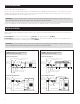
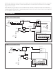
FIGURE 9 – MODEL 8140 INTERNAL SCHEMATIC
FIGURE 10 – MODEL 8141 INTERNAL SCHEMATIC
temperature above the high limit setting, it would turn off after five minutes. The control will automatically change the cycle period to four hours and
work to provide the additional 95 total minutes of ventilation (25 min/hr x 4 hours = 100 minutes, minus the five minutes of the first air sampling)
during the four-hour cycle period.
If the air temperature is still out of range, the control will automatically switch to an 8-hour cycle period, then a 12-hour cycle period and finally a
24-hour cycle period. During 8, 12 and 24 hour cycle periods, the total ventilation time increases to compensate for ventilation effectiveness as defined
in ASHRAE Standard 62.2-2010. When the cycle period automatically adjusts to 24-hours, the control will turn on ventilation to meet the requirements
even if the temperature is outside of the set limits.
7