System Installation Guide ComfortNet™ CTK03 Communicating Thermostat With wireless accessories Modulating control for up to 4 Heat/2 Cool communicating heat pump systems or up to 3 Heat/2 Cool communicating gas heat, electric cooling systems for residential and commercial applications.
System Installation Guide The ComfortNet advantage The premium Honeywell ComfortNet™ control system is easy to use, energyefficient, reliable and ensures the system is set up properly. Advanced operating algorithms built into the control delivers efficient equipment operation while providing optimal comfort.
CTK03 ComfortNet™ Communicating Thermostat Installation This booklet contains installation instructions and information on the thermostat and wireless accessories. Separate installation instructions for the furnace or air handler and outdoor AC condensing unit or heat pump are provided with the appropriate equipment. This thermostat is designed exclusively for use with the ComfortNet communicating system. Valid System Configurations This control may only be used with certain system configurations.
System Installation Guide 1 Install thermostat Thermostat Mounting Mount the thermostat approximately 5 feet from the floor on an interior wall using the included screws and anchors. Drill 3/16" holes for drywall and 7/32" holes for plaster. Do not install the thermostat where it can be affected by: • Drafts or dead spots behind doors and in corners. • Hot or cold air from ducts. • Radiant heat from sun or appliances. • Concealed pipes and chimneys. • Unheated (uncooled) areas such as an outside wall.
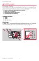
CTK03 ComfortNet™ Communicating Thermostat 1 Install thermostat Wiring Thermostat, Indoor Unit and Outdoor Unit Wire Thermostat to Indoor Unit Connect 1, 2, R and C from the thermostat to 1, 2, R and C at the Indoor Unit. Wire Outdoor Unit Connect wires 1 and 2 from the Indoor Unit to 1 and 2 at the Outdoor Unit. Install the transformer provided and connect to R and C at the Outdoor Unit. Do NOT connect R and C between the Indoor Unit and Outdoor Unit. See below.
System Installation Guide 2 Power optional accessories [If no wireless accessories are used, skip to Section 3.] Outdoor air sensor Indoor air sensor MCR32938 MCR32937 Install 2 fresh AA lithium batteries Install 2 fresh AAA alkaline batteries Portable Comfort Control MCR32939 Install 3 fresh AA alkaline batteries RedLINK™ Internet Gateway The Honeywell RedLINK Internet Gateway gives your customers remote access to home climate-control systems from any location with Internet access.
CTK03 ComfortNet™ Communicating Thermostat 2 Power optional accessories TrueSTEAM Connect the ABCD terminals between TrueSTEAM and the THM4000 Wireless Adapter. Adjust the DIP Switches on TrueSTEAM as follows when using the Wireless Adapter: DIP3: UP TrueSTEAM DIP4: UP THM4000R1000 DIP5: DOWN 1 2 3 4 5 6 ON OFF MCR31476 Entry/Exit Remote or Vent Boost Remote 1 Remove the cover. 2 Insert the CR2450 coin cell battery (included) into the slot at the bottom of the remote.
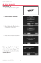
System Installation Guide 3 Setup thermostat Initial Power Up 1 Turn on AC power to the system. 2 Select Language. Press Next. 3 Select Application (Residential or Commercial). Press Next. 4 Enter a Device Name. Press Next. The thermostat will automatically identify the ComfortNet communicating equipment installed and then you will be prompted to add RedLINK accessories (page 9) and setup the Installer Options (page 12).
CTK03 ComfortNet™ Communicating Thermostat 4 Link optional accessories to wireless network If you need to return to the "Add Device" screen to add devices later, press MENU and scroll down to press INSTALLER OPTIONS. Enter the date code (password) when prompted. The date code is printed on the back of the thermostat; or press MENU > EQUIPMENT STATUS to find the date code. After you enter the password, scroll down to press WIRELESS DEVICE MANAGER and then select ADD DEVICE.
System Installation Guide 4 Link optional accessories to wireless network Portable Comfort Control CONNECT WIRELESS SETUP MCR32942 Press CONNECT on the Portable Comfort Control display screen. Press DONE when the screen displays "Connected." Press NO at the next screen to save and exit. (Or press YES to link another thermostat.) Error messages: Incompatible device cannot be connected. E1 29 E1 34 Low RF signal. Move device to a different location and try again.
CTK03 ComfortNet™ Communicating Thermostat 5 Mount optional accessories [If no sensors are used, skip to Section 6.] To install outdoor air sensor 1 Mount the sensor on a vertical exterior wall, at least 6 inches below any overhang. Choose a location protected from direct sunlight. 2 Place sensor securely in bracket, facing away from wall. M28491 M28849A To install indoor air sensor 1 Remove the wallplate and mount it 4 to 6 feet above the floor on an interior wall.
System Installation Guide 6 Installer options (ISU) To setup the thermostat, press MENU and scroll down to press INSTALLER OPTIONS. Enter the date code (password) when prompted. The date code is printed on the back of the thermostat; or press MENU > EQUIPMENT STATUS to find the date code. After you enter the password, press CREATE SETUP to setup the thermostat. A brief summary of installer options follows. You can download a complete list of all options at http://customer.honeywell.com.
CTK03 ComfortNet™ Communicating Thermostat Installer options (ISU) 6 ISU 4130 4130 4140 4140 5040 7000 7020 7110 7110 7120 7120 7120 8000 8010 8050 8060 8070 8100 8100 9000 9010 9020 9070 9080 Function ISU Entry/Exit Remote Away/Unoccupied Cool Setpoint B Entry/Exit Remote Away/Unoccupied Heat Setpoint B Entry/Exit Remote Vacation/Holiday Cool Setpoint B Entry/Exit Remote Vacation/Holiday Heat Setpoint B Indoor Sensors Used for Temperature Control B Filter Type B Number of Air Filters B Air Filter Repl
System Installation Guide Furnace User Menus Configuration (CONFIG) Sub-menu Item Indication (for Display Only; not User Modifiable) Number of Heat Stages (HT STG) Displays the number of furnace heating stages Input Rate (BTU/HR) Displays the furnace input rate in kBtu/hr Motor HP (1/2, 3/4 or 1 MTR HP) Displays the furnace indoor blower motor horse power Diagnostics (DIAG) Indication/User Modifiable Options Sub-menu Item Comments Fault 1 (FAULT #1) Most recent furnace fault Fault 2 (FAULT #2)
CTK03 ComfortNet™ Communicating Thermostat Setup (SETUP) Sub-menu Item User Modifiable Options Comments Heat Airflow Trim (HT TRM) -10% to +10% in 2% Increments (Default 0%) Trims the heating airflow by the selected amount.
System Installation Guide Air Handler User Menus Configuration (CONFIG) Sub-menu Item Indication (for Display Only; not User Modifiable) Electric Heat Size (HTR KW) Displays the size, in kW, of the selected electric heaters Motor HP (1/2, 3/4 or 1 MTR HP) Displays the furnace indoor blower motor horse power Heat ON Delay (HT ON) Displays the electric heat indoor blower on delay Heat OFF Delay (HT OFF) Displays the electric heat indoor blower off delay Diagnostics (DIAG) Sub-menu Item Indication/
CTK03 ComfortNet™ Communicating Thermostat Heat Pump/Air Conditioner User Menus Configuration (CONFIG) Sub-menu Item Indication (for Display Only; not User Modifiable) AC Tonnage (TONS) Displays the air conditioning tonnage; applies to AC and HP. Number of AC Stages (CL STG) Displays the number of air conditioning stages; applies to AC and HP. Number of HP Stages (HT STG) Displays the number of heat pump stages; applies to HP only.
System Installation Guide Status (STATUS) Sub-menu Item Indication (for Display Only; not User Modifiable) Mode (MODE) Displays the current air handler operating mode CFM (CFM) Displays the airflow for the current operating mode Cool Set-up (SETUP) Item User Modifiable Options Sub-menu Comments Cool Airflow Trim (CL TRM) -10% to +10% in 2% Increments (Default 0%) Selects the airflow trim amount; applies to air conditioner only.
CTK03 ComfortNet™ Communicating Thermostat Wiring humidifier to the IFC To change installer setup (ISU) information, see pages 12-13. Wiring TrueSTEAM to IFC THERMOSTAT IFC 1 2 R C 1 2 R C TRUESTEAM 24 V 24 V HUM HUM HUM HUM C GT R RT 1. WIRE THERMOSTAT AND TrueSTEAM AS SHOWN. 2. SET THERMOSTAT ISU 8000 TO “STEAM”. 3. SET TrueSTEAM DIP SWITCHES AS SHOWN (3 DOWN, 4 UP, 5 DOWN). GF EXT NOTE FAN INTERLOCK IS HANDLED BY THE COMFORTNET COMMUNICATION.
System Installation Guide Heat pump with outdoor temperature lockouts Outdoor temperature lockouts are optional. See Installer Setup options (ISU 3120). Outdoor temperature Electric - Backup heat allowed to run with heat pump Heat pump only Backup heat lockout Heat pump with backup heat as needed * Compressor lockout Backup heat only * No backup heat unless indoor temperature drops to selected Backup Heat Differential setting, or Backup Heat Upstage Timer expires.
CTK03 ComfortNet™ Communicating Thermostat Basic and Advanced Temperature Control Options (ISU 3010) Basic Options: The Installer Setup displays basic temperature control options which include Backup Heat Differential, Backup Heat Upstage Timer and Outdoor Temperature Lockouts. Note: Outdoor Temperature Lockouts only apply to Heat Pump applications. Advanced Options: The Installer Setup displays both Basic and Advanced Options.
System Installation Guide Humidification The thermostat reads the indoor humidity level and allows the user to set a humidification setting with or without window protection. Window Protection Window Protection limits the amount of humidity to prevent frost or condensation on windows. Window Protection (ISU 8050) requires an outdoor sensor. The maximum humidity level that is allowed ("Window Limit") is displayed on the Humidification Settings screen.
CTK03 ComfortNet™ Communicating Thermostat Dehumidification - Commercial The thermostat reads the indoor humidity level and allows the user to set a dehumidification setting. Dehumidification using the cooling system has the following methods of dehumidification control (ISU 9080): Basic: This option uses the cooling system to reach the desired humidity level. Minimum On Time and High Humidity Comfort Reset are not used with this method.
System Installation Guide Dehumidification Away Mode Dehumidification Away Mode protects the home when unoccupied for long periods of time during hot and humid weather by maintaining the desired humidity and temperature settings. To start Dehumidification Away Mode, press Menu, then press Dehumidification Away Mode. The thermostat automatically follows settings that are set by the dealer during installer setup. Press Cancel to end Dehumidification Away Mode.
CTK03 ComfortNet™ Communicating Thermostat Indoor sensor operation Temperature control The thermostat can be set to respond to its internal temperature sensor, or to an optional remote indoor sensor. If multiple sensors are used, the thermostat will respond to an average of temperatures detected at each sensor. Humidification control If optional remote indoor sensors are installed, you can choose which sensor you want to use for humidification control. You can use a different sensor for dehumidification.
System Installation Guide Alerts Log MENU > INSTALLER OPTIONS > DATA LOGS > ALERTS LOG The thermostat saves the most recent 25 alerts. It records the date, time, alert status (snoozed, dismissed, recovered), and diagnostic information to help you identify and correct problems. User Interactions Log MENU > INSTALLER OPTIONS > DATA LOGS > USER INTERACTIONS LOG Check this log to find out if a problem was caused by an accidental user error.
CTK03 ComfortNet™ Communicating Thermostat Replacing system components To remove accessories from a thermostat At the thermostat 1 Press MENU and scroll down to press INSTALLER OPTIONS. Enter the date code (password) when prompted. The date code is printed on the back of the thermostat; or press MENU > EQUIPMENT STATUS to find the date code. 2 After you enter the password, scroll down to select WIRELESS DEVICE MANAGER. 3 Press REMOVE DEVICE, then select the device you want to remove.
Regulatory information FCC Compliance Statement (Part 15.19) (USA only) This device complies with Part 15 of the FCC Rules. Operation is subject to the following two conditions: 1 This device may not cause harmful interference, and 2 This device must accept any interference received, including interference that may cause undesired operation. FCC Warning (Part 15.