
Specifications

Electrical system
chap. 6
6-22
Release 00 2002-09
Atlantic 500
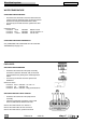
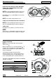
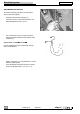
WATER TEMPERATURE
CHECKING THE DASHBOARD
• Disconnect the connector of the water thermistor and
connect (from the connector side) an electrical resistor
between the orange/red and black/white cables.
• Turn the key to ON and check the signal on the dash-
board.
Connector values:
resistance <60 Ω indication bottom of scale
resistance 80 Ω indication start of red zone
± 5 °
resistance >1090 Ω indication start of scale
CHECKING THE WATER THERMISTOR
See (CHECKING THE CONDITION OF THE COOLANT
THERMISTOR) on page 6-14.
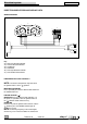
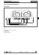
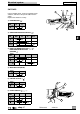
FUEL LEVEL
CHECKING THE DASHBOARD
• Disconnect the connector of the pump assembly
and connect (from the connector side) an electrical
resistor between the yellow-green and orange-black
cables.
• Turn the key to ON and check the signal on the
dashboard.
Connector values:
resistance 250 Ω
indication
1/2 scale
± 5 °
resistance 3 Ω
indication
full
resistance 820 Ω
indication empty and indicator on
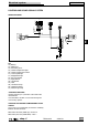
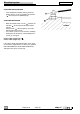
CHECKING THE FUEL LEVEL SENSOR
• Disconnect the connector of the pump/sensor
assembly.
• Connect an ohmmeter to terminals 2 and 3 and
check the indication at different fuel levels.
Correct value with full tank: less than16 Ω
Correct value with 8 liters of fuel: 300-400 Ω
Correct value with Ø liters: greater than 800 Ω
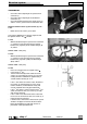
SEEN FROM ”A”
R