
Specifications

Electrical system
chap. 6
6-23
6
Release 00 2002-09
Atlantic 500
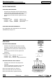
LIGHTING AND SOUND SIGNAL SYSTEM
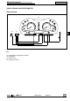
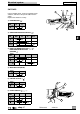
WIRING DIAGRAM
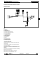
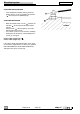
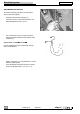
CHECKING THE HORN
Directly energize (12 V) the horn at the ends of the
two terminals.
If the horn does not work, use the relevant register.
If necessary, replace.
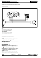
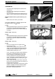
CHECKING THE HELMET COMPARTMENT LIGHT
SWITCH
Use a tester (as an ohmmeter) to check the continuity
between the two terminals.
With switch released (saddle up): value Ø Ω
With switch pressed (saddle down): value ∞
PASSING
STOP
SCROLL
19
V/RRV/R
1
N
R/Bi
24
22
R
20A
30A
R/Bi
R
V/R
V/R
R/Bi
V
C
E
A
D
F
B
26
Ar/N
B
1
25
1
15A
15A
3A
15A
15A
V/N
R/Bi
B
G
R
V/R
R
54
58
G/N
G
B
G
V/N
V
Gr
N
G/N
B
Gr
Bi
V/N
V/N
R/Bi
G/Gr
G
V
Bi
N
G/N
Gr
B
G/N
G/Gr
V
G/Gr
B
G
B
G
31
G
B
31
B
58
G
54
G
B
B
G
B
B
G
B
G
B
Bi
N
B
Bi
N
B
B
Bi
N
B
Bi
GG
35
1
27
40
31
37
39
31
50
48
49
Key
19) Battery
22) Main fuses
24) Secondary fuses
25) Helmet compartment light
26) Helmet compartment switch
27) License plate light
31) Stop/position light
35) Key commutator
37) Right dimmer
39) Left dimmer
40) Horn
48) Low beam lamps
49) High beam lamps
50) Position light lamp