
Specifications

Electrical system
chap. 6
6-24
Release 00 2002-09
Atlantic 500
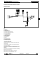
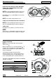
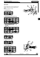
DIRECTION INDICATORS AND DISPLAY DATA
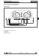
WIRING DIAGRAM
PASSING
58761612 15
EFI
TRIP
SET
W
mp/h
x1000r/min
Km/h
!
STOP
SCROLL
43
1
1
B/N
R/Bi
B/Bi
Bi/G
Az/Bi
R
Az
ABS
ABSABS
ABS
EFI
EFI
EFI
!!!!!!!
!!!!!!!!
1
Az
R
RR
Az
47
46
B/N
R
Az
B/Bi
M
Az/Bi
B/N
R/Bi
B/Bi
Bi/G
Az
R
R
R
Az
Az
39
30
29
1
Key
29) Right rear direction indicator
30) Left rear direction indicator
39) Left dimmer
43) Dashboard
46) Front right direction indicator
47) Front left direction indicator
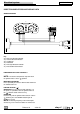
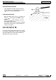
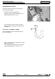
HANDLEBAR LEFT SIDE CONTROLS
NOTE The electrical components only work when
the ignition switch is in the “ ” position.
MODE BUTTON (MODE)
Press repeatedly to select the different data shown on
the multifunction LCD.
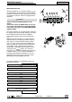
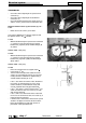
HAZARD BUTTON ( )
ENABLING Press to enable the four indicators. At
this point, it is possible to turn the ignition switch to
the “ “ position and to remove the key.
DISABLING
Insert the key into the ignition switch and turn it to the
“ ” position; press the HAZARD button again to
disable the system.
NOTE The flashing frequency of the hazard lights
will not vary, even if one of the bulbs has burned out.