
Specifications
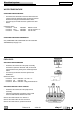

Electrical system
chap. 6
6-29
6
Release 00 2002-09
Atlantic 500
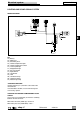
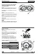
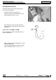
SPEEDOMETER
• Check the correct coupling of the speed sensor
connector (1).
• Check the correct coupling of the dashboard
connectors (2).
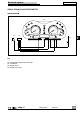
• Check the distance between the speed sensor (3)
and the screws (4) that fasten the front brake disc.
Distance between sensor (3) and screws (4): 1.5 ±
1 mm.
• Make sure that all screws (4) are fitted.
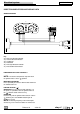
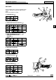
Carry out the following tests with the engine off and
the ignition switch in the “ ” position:
1
st
Test
• Without disconnecting the speed sensor connector
(1), connect a tester and measure the voltage
between the gray/blue (Gr/B) and blue/orange (B/
Ar) cables.
Correct value: > 9 V (c.c.).
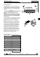
2
nd
Test
• Without disconnecting the speed sensor connector
(1), connect a tester and measure the voltage
between the gray/white (Gr/Bi) and blue/orange
(B/Ar) cables.
Correct value: > 6 V (c.c.).
3
rd
Test
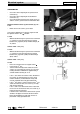
• Place the vehicle on the rear support stand
• Carry out the 2
nd
test.
• Turn the front wheel by hand so that one of the
screws (4) is level with the sensor (3). The tester
reading will move to zero V for approximately 2
seconds before returning to > 6 V.
- If the 1
st
test shows an incorrect value, disconnect
the sensor (3) and repeat the test; if the value
remains incorrect, the dashboard is faulty and
must be replaced with a fully operational one.
- If the 1
st
test shows a correct value but the 2
nd
test
shows an incorrect value, the sensor (3) is faulty
and must be replaced.
- If the 1
st
and 2
nd
test both show correct values but
the 3
rd
test has an incorrect value, the sensor (3) is
faulty and must be replaced.
- If all three tests show correct values but the speed
still does not appear on the left dial on the dash-
board, the dashboard is faulty and must be re-
placed with a fully operational one.
1
2
2