
Technical data
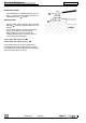

Electrical Equipment
chap. 6
6-29
6
Release 00 2002-09
Atlantic 500
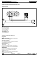
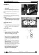
SPEEDOMETER
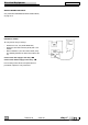
• Check the correct coupling of the speed sensor
connector (1).
• Check the correct coupling of the dashboard
connectors (2).
• Check the distance between the speed sensor (3)
and the front brake disc fixing screws (4).
Distance between sensor (3) and screws (4): 1.5 ±
1 mm.
• Check that all the screws (4) are present.
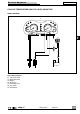
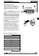
With engine off and the ignition switch in position “ ”
carry out the following tests:
1st Test
• Without disconnecting the speed sensor connector
(1) connect a multimeter and measure the tension
between the grey/blue (Gr/B) and blue/orange (B/
Ar) cables.
Correct value: > 9 V (c.c.).
2nd Test
• Without disconnecting the speed sensor connector
(1), connect a multimeter and measure the tension
between the grey/white (Gr/Bi) and blue/orange
(B/Ar) cables.
Correct value: > 6 V (c.c.).
3rd Test
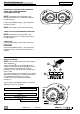
• Place the vehicle on the special rear stand
• Carry out the 2nd test.
• Manually turn the front wheel bringing one of the
screws (4) in line with the sensors (3). The
multimeter indication will give zero V for approx.
two seconds, then return to >6 V .
- If the 1st test results in an incorrect value, discon-
nect the sensor (3) and repeat the 1st test; if the
incorrect value persists, the dashboard is defec-
tive and must be replaced with one that is known
to work.
- If the 1st test results in a correct value and the 2
nd
with an incorrect value, the sensor (3) is defective
and must be replaced.
- If the 1st and 2nd tests result in a correct value
and the 3rd test with an incorrect value, the sensor
(3) is defective and must be replaced.
- If all three tests result in a correct value but the
speed does not appear to the left of the dash-
board, the dasboard is defective and must be
replaced with one that is known to work.
1
2
2
1.5 mm