
Technical data

Electrical Equipment
chap. 6
6-23
6
Release 00 2002-09
Atlantic 500
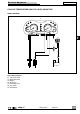
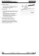
LIGHTS AND ACOUSTIC SIGNALS SYSTEM
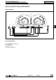
WIRING DIAGRAM
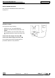
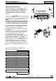
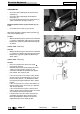
HORN CHECK
Directly supply the horn with 12 V to the two terminal
endings.
If it does not work, activate the special adjuster.
If necessary replace it with a new one.
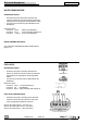
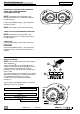
TOP CASE SWITCH CHECK
With a multimeter in ohm meter mode, verify the
continuity between the two terminals.
Value with the switch free (saddle raised) Ø Ω
Value with the switch pressed (saddle closed) ∞
PASSING
STOP
SCROLL
19
V/RRV/R
1
N
R/Bi
24
22
R
20A
30A
R/Bi
R
V/R
V/R
R/Bi
V
C
E
A
D
F
B
26
Ar/N
B
1
25
1
15A
15A
3A
15A
15A
V/N
R/Bi
B
G
R
V/R
R
54
58
G/N
G
B
G
V/N
V
Gr
N
G/N
B
Gr
Bi
V/N
V/N
R/Bi
G/Gr
G
V
Bi
N
G/N
Gr
B
G/N
G/Gr
V
G/Gr
B
G
B
G
31
G
B
31
B
58
G
54
G
B
B
G
B
B
G
B
G
B
Bi
N
B
Bi
N
B
B
Bi
N
B
Bi
GG
35
1
27
40
31
37
39
31
50
48
49
Key to wiring diagram
19) Battery
22) Main fuses
24) Secondary fuses
25) Top case light
26) Top case switch
27) Number plate light
31) Parking/stop lights bulbs
35) Key switch
37) Right switch
39) Left switch
40) Horn
48) Dipped beam bulbs
49) Full beam bulbs
50) Parking lights bulb