smart Installation / User Manual APsmart rapid shutdown system Rev1.5 2020/08/10 RSD-S-PLC TRANSMITTER-PLC TRANSMITTER-PLC OUTDOOR KIT © All Rights Reserved ALTENERGY POWER SYSTEM INC. www.APsmartGlobal.
TABLE OF CONTENTS IMPORTANT SAFETY INSTRUCTIONS---------------------------------------------------------1 Safety Instructions -----------------------------------------------------------------------------1 Symbols replace words on the equipment, on a display, or in manuals-----------------1 RSD PRODUCTS----------------------------------------------------------------------------------2 TRANSMITTER PRODUCTS---------------------------------------------------------------------3 SYSTEM WIRING DIAGRAM-------------
IMPORTANT SAFETY INSTRUCTIONS This manual contains important instructions to be followed during installation and maintenance of the APsmart RSD and Transmitter. To reduce the risk of electrical shock and ensure the safe installation and operation of the APsmart RSD and Transmitter, the following symbols appear throughout this document to indicate dangerous conditions and important safety instructions.
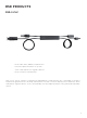
RSD PRODUCTS RSD-S-PLC · Meets NEC 2017 (690.12) requirements · Executes rapid shutdown of system when Transmitter-PLC signal is absent · Meets SunSpec requirements RSD-S-PLC meets SunSpec requirements,maintaining normal function by continually receiving a heart-beat signal from the APsmart Transmitter. The RSD executes rapid system shutdown when Transmitter signal is absent. Users can manually execute rapid shutdown using Transmitter breaker switch.
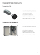
TRANSMITTER PRODUCTS Transmitter-PLC: · Meets NEC 2017 (690.12) requirements · Switch off Transmitter, rapid shutdown the output of PV modules · Meets SunSpec requirements · Equipped with single/dual core · Optional 85-264VAC power supply · Optional 180-550VAC power supply Transmitter-PLC-Outdoor Kit: · Meets NEC 2017 (690.
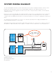
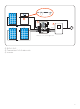
SYSTEM WIRING DIAGRAM The APsmart Rapid Shutdown System Transmitter-PLC is part of a rapid shutdown solution when paired with APsmart RSD-S-PLC, a PV module rapid shutdown unit. While powered on, the Transmitter-PLC sends a signal to the RSD-S-PLC units to keep their PV modules connected and supplying energy. RSD-S-PLC units automatically enter rapid shutdown mode when the Transmitter-PLC is switched off and resume energy production when power is restored to the Transmitter-PLC.
- + + … - + 1 + … 2 - - + + + + … 3 *PV1+ - - *PV2+ + + ~ + + *Only (+) or (-) through core ① RSD-S-PLC ② Transmitter-PLC-Outdoor Kit ③ Inverter 5
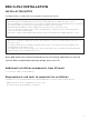
RSD-S-PLC INSTALLATION INSTALLATION NOTES Installation MUST comply with local regulations and technical rules: ① Perform all electrical installations in accordance with local codes. ② Be aware that only qualified professionals should install and/or replace the RSD-S-PLC. ③ Before installing or using an RSD-S-PLC, please read all instructions and warnings in the technical documents and on the inverter system itself as well as on the PV array.
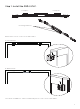
Step 1: Install the RSD-S-PLC. DC input - DC input + DC output - DC output + Mounting brackets Buckle RSD-S-PLC on the PV module frame. A. Front buckle B. Back buckle Note: Both installations can be installed anywhere on the PV module frame.
Step 2: According to the component arrangement, connect the output port of the RSD-S-PLC and connect the input port to the junction box. Input- Input + Output- Input- Output + Output- Input + Output + Step 3: Connect the RSD-S-PLC serially connected output to the inverter with a self-made DC extension cable.
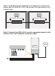
TRANSMITTER-PLC INSTALLATION Power LED V+ V- Optional power supply 85-264VAC 180-550VAC 2 1 V- V+ V- C US 259077 smart N 1 2 3 4 Power Supply Transmitter-PLC Core 1 Core 2 L Core 2 Signal LED 4 Core 1 3 Note: Transmitter-PLC terminal installation requirements: 1. A 3mm slotted screwdriver 2. The torque requirement standard: 0.2-0.4N•m Note: If there is only one core need to connect, please connect Core 1 first.
VUS C 259077 smart A P C Note: Install RSD-S-PLC before powering on Transmitter. Pas C v A a v P C Max number Of Strings Per Core : DC cable Diameter Φ5.9mm Number Of Strings Per Core (without connector) s 30 modules C 150A v ≤15 Φ6.35mm ≤15 v Φ7mm Φ8.
Drilling Guide for .
Model RSD-S-PLC Input Data (DC) Input Operating Voltage Range 8-80V Maximum Cont. Input Current (Imax) 15A Output Data (DC) Output Operating Voltage Range 8-80V Maximum System Voltage 1000V/1500V Mechanical Data Operating Ambient Temperatu re Range -40 °F to + 185°F(-40°C to + 85°C) Dimensions (without cable & connectors ) 5" x 1.2" x 0.
TECHNICAL DATA—TRANSMITTER-PLC Model Transmitter-PLC Main Electrical Data Input Voltage 12VDC Input Current 0.8A Communication P LC Power Supply Residential(optional) 85-264 VAC Input, 12VDC Output, 90 mm x 17.5 mm x 58.4 mm Commercial(optional) 180-550 VAC Input, 12VDC Output, 125.2 mm x 32 mm x 102 mm Core Data 29mm Core 11mm Core Max. Current 300A (150AX2) 75A(75AX2) Max. System Voltage 1500VDC 1500VDC Internal Opening for Wires/Outside Dimensions ~29mm/65mm ~11mm/35mm Max.
TECHNICAL DATA—TRANSMITTER-PLC OUTDOOR KIT Model Transmitter-PLC Outdoor Kit Main Electrical Data Input Voltage 12VDC Input Current 0.8A Communication PLC Power Supply Residential(optional) 85-264 VAC Input, 12VDC Output, 90 mm x 17.5 mm x 58.4 mm Commercial(optional) 180-550VAC Input, 12VDC Output, 125.2 mm x 32 mm x 102 mm Core Data Max. Current 300A(150AX2) Max. System Voltage 1500VDC Internal Opening for Wires/Outside Dimensions ~29mm/65mm Max.
ORDERING INFORMATION Transmitter 406000 29mm Dual Core Transmitter-PLC (no power supply) 406001 29mm Single Core Transmitter-PLC (no power supply) 406002 11mm Dual Core Transmitter-PLC (no power supply) 406003 11mm Single Core Transmitter-PLC (no power supply) 408004 Single Core Transmitter-PLC Outdoor Kit, 180-550VAC Power Supply 408005 Dual Core Transmitter-PLC Outdoor Kit, 180-550VAC Power Supply 408006 Single Core Transmitter-PLC Outdoor Kit, 85-264VAC Power Supply 408007 Dual Core Transm