Installation /User Manual APsmart Rapid Shutdown Device & Transmitter Rev1.1 2021/2/2 RSD-D TRANSMITTER-PLC TRANSMITTER-PLC OUTDOOR KIT © All Rights Reserve 19925 Stevens Creek Blvd, Suite 100, Cupertino, CA 95014 +1 737-218-8486 | info@APsmartGlobal.com | APsmartGlobal.
TABLE OF CONTENTS IMPORTANT SAFETY INSTRUCTIONS----------------------------------------------------------------------1 RSD PRODUCTS-----------------------------------------------------------------------------------------------2 TRANSMITTER PRODUCTS----------------------------------------------------------------------------------3 SYSTEM WIRING DIAGRAM---------------------------------------------------------------------------------4 RSD-D INSTALLATION----------------------------------------------------------
IMPORTANT SAFETY INSTRUCTIONS This manual contains important instructions to be followed during installation and maintenance of the APsmart RSD-D and Transmitter. To reduce the risk of electrical shock and ensure the safe installation and operation of the APsmart RSD-D and Transmitter, the following symbols appear throughout this document to indicate dangerous conditions and important safety instructions.
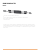
RSD PRODUCTS RSD-D · Meets NEC 2017 & 2020 (690.12) requirements · Executes rapid shutdown of system when Transmitter-PLC signal is absent · Meets SunSpec requirements · Dual-input channel The RSD-D meets SunSpec requirements, maintaining normal function by continually receiving a heartbeat signal from the APsmart Transmitter. The RSD-D executes rapid system shutdown when the Transmitter signal is absent. Users can manually execute rapid shutdown using the Transmitter breaker switch.
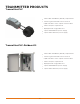
TRANSMITTER PRODUCTS Transmitter-PLC · Meets NEC 2017&2020 (690.12) requirements · Switching off Transmitter-PLC results in rapid shutdown of the output of PV modules · Meets SunSpec requirements · Equipped with single/dual core · Optional 85-264VAC power supply · Optional 180-550VAC power supply Transmitter-PLC-Outdoor Kit · Meets NEC 2017&2020 (690.
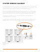
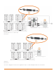
SYSTEM WIRING DIAGRAM The APsmart Rapid Shutdown System Transmitter-PLC is part of a rapid shutdown solution when paired with the APsmart RSD-D, a PV module rapid shutdown unit. While powered on, the Tansmitter-PLC sends a signal to the RSD-D units to keep the PV modules connected and supplying energy. RSD-D units automatically enter rapid shutdown mode when the Transmitter-PLC is switched off and resume energy production when power is restored to the Transmitter-PLC. This solution complies with NEC 690.
*PV1+ *PV2+ *Only (+) or (-) through core ① RSD-D ② Transmitter-PLC-Outdoor Kit ③ Inverter *PV1+ *PV2+ *Only (+) or (-) through core ① RSD-D ② Inverter* *Inverter in diagram includes an integrated SunSpec-certified Rapid Shutdown Transmitter.
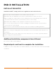
RSD-D INSTALLATION INSTALLATION NOTES Installation MUST comply with local regulations and technical rules: ① Perform all electrical installations in accordance with local codes. ② Be aware that only qualified professionals should install and/or replace the RSD-D. ③ Before installing or using an RSD-D, please read all instructions and warnings in the technical documents and on the inverter system itself as well as on the PV array.
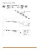
Step 1: Install the RSD-D. OUTPUT- INPUT2+ INPUT1+ INPUT2- INPUT1- OUTPUT+ Mounting brackets Buckle RSD-D onto the PV module frame. A. Back buckle B.
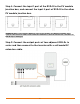
Step 2. Connect the input 1 port of the RSD-D to the PV module junction box, and connect the input 2 port of RSD-D to the other PV module junction box. WARNING: When connecting the RSD-D to only one PV module, use INPUT1 port ONLY, then connect a DC extension cable to both terminals of INPUT2 to short the unused side, otherwise the RSD-D may be damaged. Step 3: Connect the output ports of two adjacent RSD-Ds in series and then connect to the inverter with a self-made DC extension cable.
TRANSMITTER-PLC INSTALLATION Note: If there is only one core needed, connect using Core 1 terminal. Transmitter-PLC power supply must be on same AC branch circuit as inverter to meet rapid shutdown requirements. During operation, the Power LED should be lit and the Signal LED should be blinking. If the TransmitterPLC fails to work, the Signal LED will not be blinking. If the Power LED is also not lit, check the power supply first. Note: Install the RSD-D before powering on the Transmitter-PLC.
Note: Install the RSD-D before powering on the Transmitter-PLC. • Pass either positive or negative cables through cores (either both positive cables or both negative cables. Do not use one positive and one negative cable.) • Connect wires to AC side of power supply Max number Of Strings Per Core : DC cable Diameter Number Of Strings Per Core (without connector) Φ5.9mm ≤15 Φ6.35mm ≤15 Φ7mm ≤14 Φ8.
Drilling Guide for .
TECHNICAL DATA—RSD-D Model RSD-D Input Data (DC) Input Operating Voltage Range 8-80V Per Channel Maximum Cont. Input Current (Imax) 15A Per Channel Output Data (DC) Output Operating Voltage Range 16-160V Maximum Output Current 15A Maximum System Voltage 1000V/1500V Mechanical Data Operating Ambient Temperature Range -40 oF to +167 oF (-40 °C to + 75 °C) Dimensions (without cable & connectors) 5.5" x 2" x 0.8"(140 mm x 50.
TECHNICAL DATA—TRANSMITTER-PLC Model Transmitter-PLC Main electrical data Main electrical data Input Voltage 12VDC Input Current 0.8A Communication PLC Power Supply Residential(optional) 85-264VAC Input, 12VDC Output, 90 mm x 17.5 mm x 58.4 mm Commercial(optional) 180-550VAC Input, 12VDC Output, 125.2 mm x 32 mm x 102 mm Core data 29mm Core 11mm Core Max. Current 150A Per core 75A Per core Max.
TECHNICAL DATA—TRANSMITTER-PLC-OUTDOOR KIT Model Transmitter-PLC-Outdoor Kit Main electrical data Main electrical data Input Voltage 12VDC Input Current 0.8A Communication PLC Power Supply Residential(optional) 85-264VAC Input, 12VDC Output, 90 mm x 17.5 mm x 58.4 mm Commercial(optional) 180-550VAC Input, 12VDC Output, 125.2 mm x 32 mm x 102 mm Core data 29mm Core Max.Current 150A Per core 150A Per core Max.