R INSTALLATION AND OPERATING INSTRUCTIONS CHEESE MELTERS MODELS: CMC-24, -36, -48 CMP-24, -36, -48 CMW-24, -36, -48 24 Hour Toll Free Service Hot Line: 1-800-733-2203 ! WARNING: Improper installation, adjustment, alteration, service or maintenance can cause property damage, injury or death. Read the installation, operating and maintenance instructions thoroughly before installing or servicing this equipment.
Notes: GENERAL INFORMATION THIS MANUAL SHOULD BE RETAINED FOR FUTURE REFERENCE ! ! ! WARNING: Check the data plate on this unit before installation. Connect the unit only to the voltage and frequency listed on the data plate. Connect only to 1 or 3 phase as listed on the data plate. WARNING: Improper installation, adjustment, alteration, service or maintenance can cause property damage, injury or death.
! WARNING: Disconnect device from electrical power supply and place a Tag Out-Lockout on the power plug, indicating that you are working on the circuit. ! WARNING: Install per the spacing requirements listed in the installation section of this manual. We ! strongly recommend having a competent professional install the equipment. A licensed electrician should make the electrical connections and connect power to the unit. Local codes should always be used when connecting these units to electrical power.
IMMEDIATELY INSPECT FOR SHIPPING DAMAGE All containers should be examined for damage before and during unloading. The freight carrier has assumed responsibility for its safe transit and delivery. If equipment is received damaged, either apparent or concealed, a claim must be made with the delivering carrier. A. Apparent damage or loss must be noted on the freight bill at the time of delivery. It must then be signed by the carrier representative (Driver).
Overall Width Depth Height Overall Width Depth Height Dimensions (Inches) (Inches) (Inches) Dimensions (Inches) (Inches) (Inches) 17 ¼ 17 ¼ 16 17 ¼ 17 ¼ 19 ¼ 15 ¼ 19 ¼ 19 ¼ 15 ¼ CMP-36 CMC-48 CMW-48 CMP-48 16 17 ¼ 17 ¼ 16 19 ¼ 19 ¼ 15 ¼ 19 ¼ CMC-24 CMW-24 CMP-24 CMC-36 CMW-36 27 27 27 36 ½ 36 ½ 36 ½ 48 48 48 General Information Clean the unit before using. Wipe body and the inside of unit with a hot, wet cloth to remove any shipping dust or protective oil.
WALL MOUNTING (sketch 2) I. Begin by removing the two screws on the bottom of the unit along the rear. 2. Pry out the back at the bottom and remove it by pulling out and down. 3. Remove (but DO NOT discard) the insulation. 4. Use the back as a template to locate holes for wall attaching lag bolts( not supplied). 5. Fasten the back to the wall with lag bolts or with anchor fasteners, making certain the back is level securely fastened. 6. 7. Replace the insulation.
OPERATION Turn on the main switch which will turn on pilot light and start fan running. Place the product on the rack. Heaters will come on full power automatically. When the product is removed the heaters will revert to "standby" with 25% of its heat on (a slight glow may be visible). On the 48" model, either (or both) of the two top switches must be on before the heaters will light. The top switch is for the left side, and the middle switch is for the right side.
NOTICE Service work should be preformed only by a qualified technician who is experienced in and knowledgeable with the operation of commercial gas, electric, steam cooking equipment. Contact the Authorized Service Agency for reliable service, dependable advise or other assistance and for genuine factory parts.
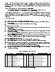
Electrical Schematic (24” and 36” models) Heaters Voltage Regulator Fan Pilot Light Main Switch Terminal Block Ground Lug Electrical Schematic (48” model) Voltage Regulator Heat Switch L.H. Pilot Light L.H. Switch R.H. Switch R.H. Pilot Light L.H. Heaters Fan Main Pilot Light 3 Pole Contactor Terminal Block Main Switch Ground Lug 9 R.H.
APW WYOTT EQUIPMENT LIMITED WARRANTY APW Wyott Foodservice Equipment Company warrants it's equipment against defects in materials and workmanship, subject to the following conditions: This warranty applies to the original owner only and is not assignable. Should any product fail to function in its intended manner under normal use within the limits defined in this warranty, at the option of APW Wyott such product will be repaired or replaced by APW Wyott or its Authorized Service Agency.
Notes: 11
R APW WYOTT Foodservice Equipment Company P.O. Box 1829 Cheyenne, WY 82003 +1 (307) 634-5801 Phone +1 (800) 752-0863 Toll Free +1 (307) 637-8071 Fax www.apwwyott.