Authorized Technician TECHNICAL MAINTENANCE MANUAL CALYPSO/TITAN/OCTOPUS SECOND STAGE
Contents COPYRIGHT NOTICE...............................................................................................................................................3 INTRODUCTION .......................................................................................................................................................3 WARNINGS, CAUTIONS, & NOTES.........................................................................................................................3 SCHEDULED SERVICE......
Calypso/Titan Second Stage Service Manual COPYRIGHT NOTICE This manual is copyrighted, all rights reserved. It may not, in whole or in part, be copied, photocopied, reproduced, translated, or reduced to any electronic medium or machine readable form without prior consent in writing from Aqua Lung America. It may not be distributed through the internet or computer bulletin board systems without prior consent in writing from Aqua Lung America. ©2004 Aqua Lung America, Inc.
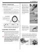
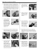
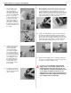
GENERAL CONVENTIONS 1. While holding the inlet fitting (13) of the second stage secure with a ¾” (19mm) open end wrench, apply 11/16” (17mm) openend wrench to the female fitting of the LP hose (25). Turn the fitting counterclockwise to loosen and remove the hose from the second stage. Remove the O-rings (24&27) from the hose and discard. Set the hose aside. 2. Slide back the hose protector (26) and check that the crimps look good and that the hose is not pulling out.
Calypso/Titan Second Stage Service Manual 4. 5. While holding the second stage secure, firmly grasp the collar of the front cover (1) which is seated over the venturi control switch (9), opposite of the inlet side. Stretch the collar over the venturi control switch, and lift the front cover off the box bottom (4) until the opposite collar can be removed from the inlet fitting (13). Closely examine the front cover to check for any tears, distortion, deterioration, or other signs of damage.
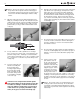
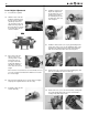
NOTE: Because the crown is o-ring sealed, it will not freely exit the valve body after it has been disengaged. The following step must be performed correctly in order to remove the crown without damaging its delicate sealing surface. 13. 14. 15. 16. Stand the valve assembly vertical on the head of the poppet (22), with the lever (18) facing up, and depress the valve body (19) to expose the locknut (16).
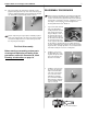
Calypso/Titan Second Stage Service Manual 20. Place the handle of the extraction tool directly over the poppet bearing (20) in the top center of the valve body (19), and press downward until the poppet bearing has dropped out. Discard the poppet bearing, and do not reuse.
4. Using tool p/n 125727, engage the slotted head of the crown (14) and drive it in clockwise as far as the tool will allow. If the tool is not available, use a medium flathead screwdriver to drive the crown in as far as it will go and then back it out 3 revolutions. 5. Stand the inlet fitting (13) vertical on a flat surface with the sealing edge of the crown (14) facing up inside. Lay the previously used LP seat (23) inside the inlet fitting, over the sealing edge of the crown. 8.
Calypso/Titan Second Stage Service Manual 11. 12. 13. Place the washer (17) over the poppet shaft (22), followed by the locknut (16), with the flat side facing down. Being careful to avoid disturbing the lever (18), turn the locknut clockwise by hand to engage the threads of the poppet, and then apply a 1/4” nut driver to turn it further; only until 1 thread of the poppet shaft is visible above the top of the locknut.
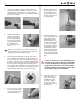
Lever Height Adjustment 17. Pressurize the regulator 18. Slide the notch of the adjusting tool 125727 across the top of the box bottom (4) The top of the lever (18) should touch the tool without causing a leak. At this point, the lever should be 2.5 mm above the rim of the box bottom. 19. 22. Install the venturi assembly into the right side of the box bottom (4). Lock it in place by inserting the retaining clip (7). You should hear it “click” as it locks into place. 23.
Calypso/Titan Second Stage Service Manual Make sure that the cover is seated evenly all the way around FINAL TESTING PROCEDURES Second Stage Air Flow Test 1. Connect the first stage regulator to a calibrated test bench and pressurize the system to 3000 (±100) psi. 2. Place the second stage mouthpiece over the mouthpiece adapter. Slowly turn the flowmeter control knob until the flow reaches a minimum of 14 SCFM (400 liters per minute).
2. Observe any bubbles arising from the submerged regulator over a one minute period. The recommended time is necessary due to slower bubble formation that occurs in smaller leaks. Bubbles indicate a leak, which requires that the system must be disassembled at the source to check sealing surfaces, assembly sequence and component positioning in order to correct the problem(s). NOTE: Extremely small leaks may be better detected by applying a soap solution or Snoop™ to the leak area.
Calypso/Titan Second Stage Service Manual Table 1 - Troubleshooting Guide SYMPTOM Leak or freeflow at 2nd Stage Insufficient purge flow or work of breathing too high Water leak in 2nd stage during inhalation POSSIBLE CAUSE TREATMENT 1. MP too high 1. Refer to First Stage Troubleshooitng Guide 2. The LP seat (23) is worn or damaged 2. Replace the LP seat 3. The crown orifice (23) is not correctly adjusted 3. Readjust the crown orifice 4. The lever (18) is bent 4. Replace the lever 5.
Table 2 - Recommended Tool List PART NO. DESCRIPTION APPLICATION 111610 I.P.
Calypso/Titan Second Stage Service Manual Table 4 - Recommended Lubricants & Cleaners LUBRICANT / CLEANER ® Christo-Lube MCG-111 APPLICATION All O-rings seals SOURCE Aqua Lung, PN 820466, or Lubrication Technologies 310 Morton Street Jackson, OH 45640 (800) 477-8704 CAUTION: Silicone rubber requires no lubrication or preservative treatment. DO NOT apply grease or spray to silicone rubber parts. Doing so may cause a chemical breakdown and premature deterioration of the material.
Procedure A Cleaning & Lubrication Aqua Lung and Apeks Regulators and Nitrox When it comes to issues of nitrox safety and compatibility, the concerns lie primarily with the regulator’s first stage as it is subjected to high inlet pressures. High inlet pressures lead to adiabatic compression or heating of the gas. The Aqua Lung or Apeks regulator product described in this manual, when properly cleaned and assembled, is authorized for use with enriched air nitrox (EAN) that does not exceed 40% (EAN 40).
Calypso/Titan Second Stage Service Manual Table 5 - Torque Specifications PART NUMBER DESCRIPTION / KEY NUMBER TORQUE APF124563/APF124566 LP Hose Female Fitting (25) 40±3 inch-lbs 104106 Inlet Fitting (13) 45±5 inch-lbs Table 6 - Test Bench Specifications TEST CONDITION ACCEPTABLE RANGE Leak Test Inlet 2,500-3,000 (±100) psig No leaks allowed Opening Effort Inlet 2,500-3,000 (±100) psig Intermediate pressure 135-140 psi Calypso/Titan: +1.0 - 1.6 in. H20 Octopus: +1.2 - 1.8 in.
NOTES
Calypso/Titan Second Stage Service Manual Titan • Calypso • Octopus (2004 - present) Exploded Parts Diagram 25 26 24 27 1a 1b 1c Key # Part # Description n/a ---- 125740 n/a ---- 125835 n/a ---- 900010 Calypso 2nd Stage only Titan 2nd Stage only Service Kit 1a ----- 125732 1b ----- 125719 1c ----- 125724 2------- 124509 3------- 125705 4------- 125721 5------- 129154 6a ----- 109438 6b ----- 104138 7------- 125707 8------- 820015 9------- 125706 10 ----- 129174 11 ----- 125702 12 ----- 82001
Authorized Technician TECHNICAL MAINTENANCE MANUAL CALYPSO/TITAN/OCTOPUS SECOND STAGE Aqua Lung America 2340 Cousteau Court, Vista CA 92081 Tel: 760-597-5000 / Web: www.aqualung.