
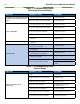
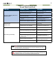
Troubleshooting guide

11
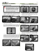
CAUTION: Before proceeding, visually inspect the
cylinder according to Compressed Gas Association
(CGA) standards (pamphlet CGA C-6.1--1984, "STAN-
DARDS FOR VISUAL INSPECTION OF HIGH PRES-
SURE ALUMINUM COMPRESSED GAS CYLINDERS".
This inspection requires a visual inspection light.
If the cylinder does not pass the visual inspection,
it must be serviced or replaced with a new cylinder
before it can be assembled and lled.
37
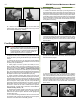
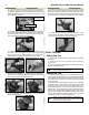
5. Lightly lubricate the rst stage body threads. Pass the pis-
ton shaft through the spring. While pressing down on the cap,
handtighten the cap onto the rst stage by turning clockwise.
Tighten the cap with an adjustable spanner wrench until the
cap stops against the rst stage body.
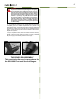
8. Attach a 9/16" socket adapter to a torque wrench and tighten
the ll adapter port (23) to 90±3 in/lbs. Do not overtighten -
damage to the ll port adapter will result.
6. Install a new lubricated o-ring (25) onto the shaft of the
check valve (26). Install a new lubricated o-ring (22) onto the
ll port plug (21).
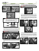
4. Place the spring (35) into the body. Press the piston into
the cap (30) so that the piston head is seated at against the
cap. Verify there is no dirt or damage to the smooth inner sides
of the cap.
7. Insert the check valve (26), o-ring side rst, into the male-
threaded end of the ll adapter port (23). Install a new lubricated
o-ring (22) onto the ll adapter port. Lubricate the threads,
then thread the ll adapter port into the lower of the two high
pressure ports.
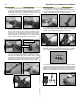
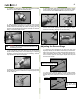
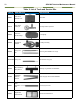
REASSEMBLY PROCEDURE
*Lubricate all O-rings with Christo-Lube
®
before assembly.
1. Install a new, lightly lubricated o-ring (37) over the cylinder
threads so that it is seated against the rst stage body. Lubricate
the rst 4 to 5 threads on the rst stage body with Christo-
Lube
®
. Do not use an excessive amount.
First Stage Reassembly
2a. Thread the rst stage into the cylinder until handtight. At-
tach a 1 3/16" crowfoot adapter to a torque wrench. Apply a
strap wrench to the cylinder. While holding the cylinder rmly,
tighten the rst stage body to a torque value of 25 ± 2 ft/lbs.
3. Install a new lubricated piston shaft o-ring (33) and piston
head lubricated o-ring (31) onto the piston (32). Closely inspect
the edges of new HP seat (34). One edge is sharp and one edge
has a chamfer. With the chamfered edge facing outward, press
the HP seat into the small, recessed hole in the end of the pis-
ton. The easiest method is to place the chamfered edge down
on a at surface and simply press the piston down over it.
32
33
34
35
30
29
23
26
2. Place the cylinder in the Bottle Vice or Vice Insert. Attach
a 1 3/16" crow foot adapter to a torque wrench. Tighten the
regulator body to 25 ± 2 ft/lbs OR: