
Specifications
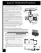

30
AquaLink
®šš
RS Heater Connection
Installation Guidelines (Continued)
Guidelines for RayPak Heaters:
For RP2100: (Models: P-R185A to P-R405A,
C-R185A to C-R405A, P-R185AL to P-R405AL,
C-R185AL to C-R405AL, from Catalog #6000.52-X)
1. For the 2-wire/1 function configuration, connect the orange/
black and black/orange wires to one contact and the yelow/
black wire to the other contact.
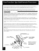
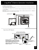
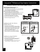
Guidelines for Purex Heaters:
For MiniMax and Tropical Isle Pool and Spa Heaters:
1. Remove the heater service door.
2. Separate the black wire (common) from each other
(see diagram at right).
3. Connect the wires from the AquaLink RS P.C. Board to the
two black wires as shown. The violet and red wires remain
unused.
4. Turn heater toggle switch ON, and thermostat(s) to MAX.
5. When connecting an AquaLink RS Controller to a Purex
heater, Purex requires that you install the low voltage
thermostat wires in separate conduit from ANY line
voltage wires. Failure to do so will cause the thermostat
relay to react erratically.
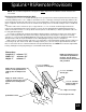
Guidelines for Hayward Heaters:
For HM2 Models 150, 200, 250, 300, 350 and 400:
1. Remove heater service door.
2. Remove factory-installed wire-nut between two red wires
labeled "CONNECTION FOR FIELD INSTALLED
CONTROL SWITCH".
3. Wire-nut two heater wires from AquaLink RS P.C. Board
to the two red wires as shown in the diagram to the right.
4. Set the thermostat selector switch to ON, HIGH or SPA
and set the heater thermostat(s) to maximum.
Heater Wiring
with AquaLink RS
Heater Wiring
Before Modification
VIO
BLK
BLK
RED
VIO
BLK
BLK
RED
Heater Wiring
with AquaLink RS
Heater Wiring
Before Modification
To AquaLink RS
System
P7
Terminal
Heater Wiring with
AquaLink RS
Typical RayPak Heater Connection
Typical Purex Heater Connection
Typical Hayward Heater Connection
Limit
Switch
Limit
Switch
Limit
Switch
Limit
Switch
Pressure
Switch
Pressure
Switch
Factory
installed
wire nut
Wires to
AquaLink RS
RS
Wires