
Specifications
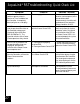
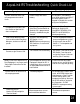


34
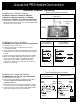
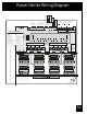
Power Center Wiring Diagram
Aux. 4 Relay Aux. 7 Relay
Aux. 6 RelayAux. 5 Relay
Water Temp.
Sensor
F ilter P um p Re lay Aux. 3 Relay
Aux. 1 Relay
Line One
Low Voltage Raceway (do not run high voltage wire in this compartment)
Line Two
Load One
Load Two
Aux. 2 Relay
Grounding Bar
Wire Nutto
120 VAC Power
System Po wer
Intake
JVA
Cleaner
JVA
Solar
Pump
Return
JVA
Solar
JVA
Elect.
Heater
Red
Black
Green
White
Yellow
Green
Black
Red
Brown
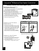
To R em o te
(brow n term . bar)
To Sens ors, etc.
(green term. bar)
To Controller
(red term . bar)
4321 654321
Blue
Red
Not Used
Black
Not Used
Red
Black
Solar
Sensor
Low Voltage
Heater
F.Pump Aux. 1 Aux. 2 Aux. 3
Relay Sockets (24 VDC output)
Aux. 7Aux. 6Aux. 5Aux. 4
Relay Sockets (24 VDC output)
Relay Sockets
(24 VDC output)
JVA S ockets
(24 VAC output)
#OFF
1Aux1
2 1 spd pump
3Aux3
4CoolDown
5 See Manual
6 Spare Aux Pool
7NotUsed
8 Gas Heater
B attery
(9Volt)
Dip Switch S ettings
Factory Set Optional Set
ON
Cleaner
2 spd pump
S pa S pillov er
Disabled
See Manual
Spare Aux Spa
Not Used
Heat Pum p