Operating & Service Instructions -for- HP7 Microprocessor Controller Includes Connection of External Controllers Dealer & Service Version Not for Distribution to Owners 2737 24th Street North St. Petersburg, FL 33713 800-786-7751 www.aquacal.
Revised 10/14/03 TABLE of CONTENTS GENERAL DESCRIPTION of HP7 CONTROLLER.................................................4 HP7 CONTROLLER SPECIFICATIONS....................................................................4 Inputs: ........................................................................................................................................................4 Outputs:......................................................................................................................
2. 3. 4. 5. 6. 7. Time Delay [dEL] : ......................................................................................................................12 Configuring for External Controllers [JAO] or [FS2]: ................................................................12 Water Sensor calibration [tSC]… ................................................................................................13 Defrost Sensor Calibration [dSC]… ....................................................................
GENERAL DESCRIPTION of HP7 CONTROLLER The HP7 is a powerful microprocessor control designed for use in swimming pool & spa heat pumps. The control features 3-digit temperature and set point display, with programming changes easily performed via simple 3-button (key) operation.
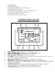
Control Features: ♦ Compressor Operation ♦ Refrigerant Circuit Hi & Low-Pressure Lock Out ♦ Water Pump Option (Call Flex) ♦ Precise Evaporator Temperature Control (Defrost Management) ♦ Anti Short Cycle Timer (4-Minute Restart Delay) ♦ Precise Water Temperature Control ♦ Corrosion Protection (Conformal Coating) CONTROL PANEL LAYOUT (Appearance will vary between model lines) 1) 2) 3) 4) 5) 6) 7) 8) 9) DOWN ARROW – Reduces temperature setting. Turn heater off.
CONTROL PANEL SYMBOLS UNIT is HEATING WATER TEMPERATURE SET POINT ACTUAL WATER TEMPERATURE POOL SELECTION SPA SELECTION 6
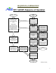
SEQUENCE of OPERATION HP-7 (6200P) Sequence of Operation LINK to Codes OPERATIONAL CODES ______________________ "FS"...Defrost Mode Normal Operation in Colder Weather FAILURE CODES ______________________ CSE- Control System Error dPC-Defrost Sensor Shorted dPO- Defrost Sensor Open PC- Water Sensor Shorted PO- Water Sensor Open LP- Refrigerant Low Pressure HP5- 5 High Press.
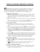
START UP & SETTING OPERATING CONTROLS LEVEL-1 (Owner) ACCESS NOTE: Covered within this section are features and settings typically accessed first by the installer, and then remaining accessible by the end user (owner). These features reside at the Level-1 access point within the microprocessor. (Please see page-11 for information concerning Level-2, service-related access.) 1. Applying Power to The Controller: A.
5. Changing The Pool Temperature Set Point: A. Using the Pool / Spa key, select the POOL temperature set point. The pool set point indicator light will confirm your selection by lighting. B. The pool temperature set point range is adjustable from 60°F. to 95° F (104 °F in latest models). using the Up ⇑ or Down ⇓ arrow keys. The desired temperature can be selected by briefly depressing the arrow keys, or by holding them down to scroll the temperature up or down. 6.
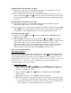
5) With [ELC] displayed, use the Up or Down arrow keys to select a lock code number. The factory set lock code is “17”. Not depressing any buttons for 15seconds will allow the control to save the selection and return to the normal operating mode. Pressing the Pool / Spa key will also save the selection and step to the next menu parameter [CFO] (Call Flex Options); 6) Once the ULC option has been enabled, depressing any key will display [000] (prompting the entry of the correct lock code number).
10. Fan Speed Control… This option is not applicable to any current models. If option present, factory default setting of “80” MUST remain. Controllers Version .06 or newer will not contain a FAN option. LEVEL-1 DISPLAY CODES Menu Codes Description Function [FLO] No water flow Displayed Code Message: Appears whenever the circulating detected pump is off, or when the heater is not receiving correct water flow.
WARNING !!!! Dealer & Service Center Use Only SERVICE & SET UP FEATURES LEVEL-2 ACCESS (Includes Configuration for External Controllers) 1. Entering Service Menu: A. To enter the service menu level, depress and hold both the Up ⇑ and Down ⇓ arrow keys simultaneously until the code message [CF1] (Celsius Fahrenheit Selection) is displayed. (NOTE: If [000] displays, User Lock Code is enabled, and the ULC pass code must be entered before proceeding.
WARNING !!!! Dealer & Service Center Use Only 3.2: Configuring for External Controllers not Equipped with an “OFF” Position Switch, and All Double-Function Air Switch Controllers. (Also see Appendix Item “B”) 3.3 Remote Flow Switch / Automatic Thermostat Switching [FS2]: (Also see Appendix Item “C”) A. Follow the steps 1a. through 1d. above to enter the service menu. Once [dEL] is displayed, press the Pool / Spa key twice to display [FS2]. B.
WARNING !!!! Dealer & Service Center Use Only B. Remove the unit front panel to gain access to the defrost sensor . The defrost sensor will be found strapped to the suction line in combination with the TXV sensing bulb, or, in some models, the defrost sensor will be connected to the suction line independent of the TXV bulb; C. Carefully remove the insulation from around the sensor area; D.
WARNING !!!! Dealer & Service Center Use Only 7. Changing Service Lock Code & “Backdoor” Entry… A. Changing the Code… The factory default Service Lock Code is “50”. Service personnel are strongly advised to retain the factory default setting. However, should unauthorized access to the Level-2 (Service) menu be suspected, it may be useful to select a code other than “50”.
WARNING !!!! Dealer & Service Center Use Only 8) [DEL] will display (At this point you have entered the service menu, and servicelevel programming will be possible.); 9) Push Pool/Spa pad until [LOC] appears on readout for the second time; 10) Push the up arrow,…The current, correct lock code will display. Using the up or down arrow, the code can now be changed back to back to the factory default: “50”, or the code may be set to any number ranging [000] to [999].
WARNING !!!! Dealer & Service Center Use Only LEVEL-2 FAULT CODES Message Error Description [dPO] Defrost Sensor Open Water Temperature [PO] Sensor Open [dPC] Defrost sensor shorted Water temperature [PC] sensor shorted Refrigerant system [LP] low pressure switch open Refrigerant system [HP] high pressure switch open [FLO] Low or no water flow detected Heater in defrost [FS] mode [CSE] Control system error Possible Cause Cut or loose sensor wiring Cut or loose sensor wiring Short circuit in defrost senso
WARNING !!!! Dealer & Service Center Use Only APPENDIX Connecting to, and Configuring Microprocessor for, External Control: • A: Jandy and Pentair/Compool Brand External Controllers Equipped with an “OFF” Position • B: External Controllers NOT Equipped with OFF Setting • C: Remote Flow Switch Connection • D: Call/Flex Option 18
WARNING !!!! Dealer & Service Center Use Only Connecting Specific Jandy Or Pentair/Compool Controllers (See application table within) Appendix- A Instructions For Connecting Specific Jandy Or Pentair/Compool Controllers To AquaCal’s HP7 Microprocessor The microprocessor terminal block, labeled X,Y,Z, is located on the low-voltage portion of the MICROPROCESSOR POWER BOARD. (See figure 1, below.) Figure-1 Controllers Suitable for this Application: Jandy and Compool controllers have similar features.
WARNING !!!! Dealer & Service Center Use Only Warning ! MAKE CERTAIN POWER SUPPLY TO HEATPUMP and CONTROLLER IS DISCONNECTED PRIOR TO CONTINIUING. FAILURE TO DISCONNECT ELECTRICAL POWER MAY RESULT IN SERIOUS INJURY OR DEATH. 1. String 18/2 cable from the controller to the heat pump. 2. Locate the MICROPROCESSOR POWER BOARD inside the heat pumps electric box. (See figure 1) 3.
WARNING !!!! Dealer & Service Center Use Only Warning ! MAKE CERTAIN POWER SUPPLY TO HEATPUMP and CONTROLLER IS DISCONNECTED PRIOR TO CONTINIUING. FAILURE TO DISCONNECT ELECTRICAL POWER MAY RESULT IN SERIOUS INJURY OR DEATH. 1. String 18/3 cable from the controller to the heat pump. 2. Locate the MICROPROCESSOR POWER BOARD inside the heat pumps electric box. (See figure 1) 3.
WARNING !!!! Dealer & Service Center Use Only Connecting Controllers Not Equipped With an OFF Setting (See application table within) Appendix- B HP-7 ….
WARNING !!!! Dealer & Service Center Use Only Connecting a Remote Flow Switch Appendix- C Installing A Remote Flow Switch For Automatic Thermostat Switching A Remote Flow Switch kit is designed to allow automatic selection of the thermostats on AquaCal heaters equipped with HP7 Microprocessors with LED display. The Microprocessor will receive a signal from the flow switch, which can be installed in either the pool return line or the spa return line. Follow the instructions below for either installation.
WARNING !!!! Dealer & Service Center Use Only FLOW SWITCH INSTALLED IN POOL RETURN LINE FIGURE 1 SPA Return Line Installation 1. Disconnect power to the AquaCal Heater. 2. Remove front access panel and the electric box cover (if equipped) on the heater. 3. String the flow switches cable through an access hole in the side of the heater and into the electric box. 4. Locate the Microprocessor Power Board inside the electric box. (see figure2) 5.
WARNING !!!! Dealer & Service Center Use Only FLOW SWITCH INSTALLED IN SPA RETURN LINE FIGURE 2 For Assistance Call AquaCal @ 800-786-7751 Mon. – Fri.
WARNING !!!! Dealer & Service Center Use Only Installing a Call Flex Kit Appendix- D Installing a Call Flex Kit for Time Clock Management - Heaters Equipped With HP7 Microprocessor The CALL-FLEX is installed to manage the time clock to the desired heating style of the pool heat pump owner. With CALL-FLEX, owners select one of three heat modes: Call Mode The heater "overrides" the filter pump timer when the pool water drops below the temperature set point.
WARNING !!!! Dealer & Service Center Use Only Diagrams 27
FIGURE 2 CAUTION ! ONLY NON-ENERGIZING (“DRY”) CIRCUIT SHOULD BE CONNECTED; NEVER APPLY EXTERNAL-SOURCE VOLTAGE TO THE HP7 MICROPROCESSOR TERMINAL BOARD. FAILURE TO FOLLOW THESE INSTRUCTIONS WILL RESULT IN EQUIPMENT DAMAGE. WARNING ! DISCONNECT ALL ELECTRICAL POWER WHILE PERFORMING THIS WORK. FAILURE TO FOLLOW THIS WARNING MAY RESULT IN SERIOUS INJURY OR DEATH. INSTALLATION 1. Disconnect power to the AquaCal Heater. 2. Remove front access panel and the electric box cover (if equipped) on the heater. 3.
2737 24th Street North St. Petersburg, FL 33713 800-786-7751 www.aquacal.