Pool and Spa Heat Pump Owner’s Manual and Installation Guide PN: LTP0009 01/12/04 Models: T65 T115 T135 (Also Applies to All C115 Models) ATTENTION INSTALLER: THIS DOCUMENT IS PURCHASER’S PROPERTY AND IS TO REMAIN WITH THE HEAT PUMP OWNER 1/7/041 AQ Technical, 9/24/04
1-800-786-7751 NOTES ___________________________________________________________________________________ __________________________________________________________________________________ ___________________________________________________________________________________ _________________________________________________________________________________ _________________________________________________________________________________ __________________________________________________________________________
TABLE OF CONTENTS WELCOME TO THE TEAM ------------------------------------------------------------------ 4 IMPORTANT FEATURES OF YOUR NEW HEAT PUMP -------------------------------- 5 SAFETY INFORMATION --------------------------------------------------------------------- 6 QUICK START & STOP ----------------------------------------------------------------------- 8 PHYSICAL CHARACTERISTICS & PERFORMANCE ----------------------------------- 9 Dimensional Information - TropiCal Models T65 and T115 ------------
Welcome to the Team Dear Owner: C ongratulations on your wise decision to make an AquaCal heat pump part of your home. Since 1981, AquaCal has maintained the worldwide lead in the manufacture of swimming pool & spa heat pumps. Your new heat pump is not only a great investment, but also the most cost effective method available for heating pools and spas.
IMPORTANT FEATURES OF YOUR NEW HEAT PUMP ThermoLink Heat Exchanger: a a a ThermoLink Heat Exchanger Electronic Controller: The heart of your heat State-of-the-art, solid-state pump is the patented electronic controller, mainThermoLink heat extains water temperature changer. The primary within 1ºF of set point. Concause of premature troller also permits user to heat pump demise is predefine different Pool and the failure of the heat Spa water temperature set exchanger. Ordinary (135-Series) points.
SAFETY INFORMATION Used and maintained properly, your heat pump will provide year-upon-year of safe and economical service. However, as with any mechanical or electrical device, to get the most from your heat pump–while insuring personal safety for you and others–certain operational and maintenance factors must be observed.
Heater NOT Repairable by Owner WARNING ! Failure to heed the following may result in permanent injury or death. Heat pumps contain no owner-repairable components. Repairs must not be attempted by untrained and/or unqualified individuals. If service is deemed necessary, contact installing dealer or AquaCal Customer Support at (800) 786-7751. Refrigerant Circuit Service Only by Qualified, EPA Certified Technician WARNING ! Failure to heed the following may result in permanent injury or death.
T QUICK START & STOP his brief information is provided as an aide to installers, service personnel, and owners. The intent of this section is to provide rapid access to (only) very basic operational information. Individuals who will be routinely using, installing, maintaining and servicing this heat pump are strongly encouraged to read this entire manual. If uncertain about any instructions given herein, AquaCal Customer Support (800-786-7751) should be contacted for additional information. 1. 2. 3. 4.
PHYSICAL CHARACTERISTICS & PERFORMANCE Dimensional Information - TropiCal Models T65 and T115 A NOTES: 1. ALL DIMENSIONS IN INCHES 2. MIN.
Dimensional Information - TropiCal Model T135 A NOTES: 1. ALL DIMENSIONS IN INCHES 2. MIN.
TropiCal: Table of Specifications MODELS: T65”X”-A T65”X”-B T115 “X”-A T115 “X”-B T135 “X”-A T135 “X”-B Air ºF / Air ºF… 80/50 55000/37000 55000/37000 104,000/70,000 104,000/70,000 126,000/82000 126,000/82000 COP 4.8/3.7 4.8/3.7 4.3/3.2 4.3/3.2 5.7/4.0 5.7/4.0 Air ºF / Air ºF… 80/50 51000/34000 51000/34000 97,000/65,000 97,000/65,000 119000/77000 119000/77000 COP 4.5/3.6 4.5/3.6 4/3.1 4/3.1 5.4/3.8 5.4/3.8 Kilowatt Input (80% RH) 3.4 3.4 7.1 7.1 6.5 6.
Refrigerant Circuit Performance Charts For use with Troubleshooting Refrigerant Circuit Problems guide, following charts. !" # $ ! )"# $# % $# ( ) ' "* !" &+" (! + ( ,* !& &+, +" " ) &, + / 01 "# $#% $# &'( . !"# $#% $# !" # $ ! '" ( ) "* &+ "# $# % $# &&& '( & &* ,, &( &) +& ) " &( ' )"# $# % $# %& / 01 &** . !"# $# % $# !" # $ ! "# $# % $# &, ,+ && "! )"# $# % $# $ '( $)* ,& " " ! &" !, &) &" !* &" &" ) " + / 01 +( .
Guide: Troubleshooting Refrigerant Circuit Problems Refrigerant Circuit Service Only by Qualified, EPA Certified Technician WARNING ! Failure to heed the following may result in permanent injury or death. Heater contains refrigerant under high pressure. Repairs to the refrigerant circuit must not be attempted by untrained and/or unqualified individuals. Service must be performed only by qualified HVAC technicians. Recover Refrigerant to relieve pressure before opening system.
TXV Stuck Open: • Head pressure will be slightly to moderately low; • Suction pressure will be slightly high to very high; • Amperage (not a reliable indicator of this condition); • Liquid Sub-Cooling will be lower than normal; • Superheat will be minimal or nonexistent; • Suction line, and possibly a large portion of compressor, will be very cold and possibly “sweating”.
Code Required Clearances: u In addition to the previously stated clearance requirements, follow all applicable local, state, and national requirements relative to spacing from other objects or equipment. Typical Installation Clearances Rain run-off must be directed away from unit 24 - Inches (Rear) Overhang with gutter 5 ft. minimum clearance, overhead 30” minimum clearance, front 24 - Inches (Side) 24 - Inches (Side) 2 ft.
Plumbing Requirements Overview: When planning plumbing system layout, reference the plumbing schematics following this section as a guide to the sequence of equipment, valves, fittings, etc. The plumbing configurations for typical installations are diagrammed. In operation, it is imperative the heat pump receive water flow within the minimum-maximum ranges specified for the particular heat pump.
Plumbing Schematics 17
Water IN & OUT Connections For proper operation and maximum efficiency, piping coming from the pump and filter MUST be connected to the "IN" port of the heater. Likewise, connect piping returning to the pool/spa to the "OUT" port of the heater. See drawing below. Electrical Requirements WARNING! Failure to heed the following may result in permanent injury or death. Installation made by unqualified persons can result in hazards to the installer and others.
Code Requirements: u The electrical installation must conform to the most current version of the National Electrical Code, NFPA No. 70, and all applicable local and state codes. u National Electrical Code, article 680; Swimming Pools, Fountains, and Similar Installations, shall apply. u National Electrical Code, article 440, Air-Conditioning and Refrigeration Equipment, shall apply. Reference Equipment Data Plate: u All TropiCal heat pumps have their data plates located on the left, exterior, side panel.
START-UP & OPERATION Getting Familiar with Controls T135/115/65 Control Panel Layout 1. POOL TEMPERATURE CONTROL - Set this knob for desired pool water temperature 2. POOL/OFF/SPA -Toggles between pool temperature/off/spa temperature 3. SPA TEMPERATURE CONTROL - Set this knob for desired spa water temperature 4. POWER LIGHT - Indicates electrical power is supplied to the heater 5. FLOW LIGHT - Indicates water pressure (Flow) is present at the heater 6.
Overview of Controls (Please refer to control panel diagram on previous page.) POOL/OFF/SPA Toggle Switch: With the toggle switch in the OFF (O) position, the heater will be prevented from operating (however, there may be power to the unit; see "Power Light On", below).
Note-Five (5) Minute Time Delay Function: The heater controls contain a solid-state time delay module. This time delay feature prevents damage to the compressor should electrical power be repeatedly interrupted, or if the heat pump were to come under any other circumstances leading to an on-off-on-off cycling condition.
Pool and Spa Combination Heating Everything stated for heating a pool applies for heating a spa; only the volume of water being heated is different. TropiCal model heat pumps come equipped with two thermostats. One thermostat is for the pool and the other is for the spa.
Volume of Pool (Length X Width X Average Depth) = _________ Pool Cubic Feet X Gallons per cubic ft.(7.5) = _________ Pool Gallonage X Pounds per Gallon (8.3) = _________ Pounds of Water How many degrees do you want to raise the temperature of the pool? # of Degrees _________ X Pounds of Water (per above) = __________ BTU’s Required BTU’s Required (per above) ___________4 BTU Output of Heater = ______ Hrs. of Operation Optional Cold Weather Adjustment Factor: Hrs. of Operation (per above) ______ X 1.
Planned Maintenance Program Just as you would have yearly service performed on your air conditioning system, regular inspection & maintenance of your AquaCal heat pump will insure highest operating efficiencies while also protecting your investment, potentially extending the useful life of your heat pump far beyond the warranty period.
WARNING ! Failure to heed the following may result in permanent injury or death. POSSIBLE ELECTRIC SHOCK HAZARD . . . Should you decide to wash the unit via water hose, disconnect all power to the pool equipment pad- including, but not limited to: The heat pump, water pump, and any and all other electrical equipment. Do NOT sprag water directly into electrical components. Do NOT restore electrical power until such time as all water has dried completely.
Maintaining Proper Clearances Around Heater u For maximum efficiency, proper air flow clearances around heater must be maintained. u It is important to keep the area around your heat pump clear of items such as shrubs and bushes, lawn furniture, chemicals containers, etc. These items can prevent air from circulating properly through the heater, and will result in inefficient operation or damage to components inside the heat pump.
Winterizing Procedure: 1. Disconnect all electrical power to the heater; turn OFF circulating pump. 2. At the two (2) water connection unions, disconnect the plumbing to the heater (removal is counterclockwise). 3. Locate the drain plug at lower, right-hand, front corner of heater. (See Figures 1 & 2, below.) 4. Using a 5/8", box-end wrench, remove the drain plug (removal is counterclockwise). 5.
TROUBLESHOOTING Common Troubleshooting Issues Heat Pump Not Running Is the power light lit? If not, ensure the main breaker (located at the power supply panel) and the disconnect switch (located near the heat pump) are both turned ON. Is the flow light lit? If not , check to be sure that the circulating pump is operating and the filter is clean. There may also be a valve positioned incorrectly allowing water to bypass the heat pump. Be sure water is flowing through the heater.
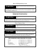
Troubleshooting Flow Charts Heater Fails to Operate Analog Controls - 12/22/03 START START Is the thermostat turned UP, thetoggle thermostat turned UP, andIsthe or rocker switch andselecting the toggle or rocker either the switch selecting either the SPA or POOL SPA or POOL thermostat ? thermostat ? Yes No Check to be sure the Check the power lightto is be on.sure If the power light is on. If the power light is off, check power light iscircuit off, check for a tripped for a tripped breaker.
Heater Running but Not Heating Analog or Digital Controls - 12/22/03 START START Is the air being discharged thetop airof being discharged out ofIsthe the heater 9-12 out of the top of the heater degrees cooler than the 9-12 degrees cooler outside air? than the outside air? No Is the defrost light on, or Is the defrost light: "FS" on, or? does the display read does the display read : "FS" ? Yes Yes The defrost light or "FS" The defrost light orair"FS" displayed indicates displayed indicates air tempe
Determining Water Leaks vs. Condensation All Analog/Digital Air Source Heat Pumps - 12/22/03 START Is the START flow light on Is thethe flow light on and unit and the unit heating? heating? Yes When the heater is operating, thetoheater is operating, it isWhen normal produce up to 8 it is normal to produce up to 8 gallons of condensation (water) gallons (water) per hour.of Ifcondensation water drainage per excessive, hour. If water drainage seems proceed to seemsTESTING. excessive, proceed to TESTING.
Heater Short Cycling Analog Controls - 12/22/03 START *Any operation described in this If the heaterSTART is turning on and If the turning on and off heater every 5isminutes: off every 5 minutes: Make sure all water valves are Make sure position, all water allowing valves are in the correct in the correct allowing water to flow position, through the waterBe to sure flow filters through the heater. and heater. Be sure filtersare and pump skimmer baskets pump skimmer clean.
REPLACEMENT PARTS CONTROL BOX COMPONENTS VOLTAGE : 1/60/208-230 VOLTAGE : 3/60/208-230 T65”X”-A T115”X”-A T135”X”-A T65”X”-B 115”X”-B PART DESCRIPTION THERMOSTAT,HONEYWELL POTTED PART NUMBER 6270 6270 6270 135”X”-B PART NUMBER 6270 6270 6270 THERMOSTAT, AMBIENT AIR (RANCO) 7048 7048 7048 7048 7048 7048 TIME DELAY, 5 MINUTE ON BREAK 6102A 6102A 6102A 6102A 6102A 6102A TERMINAL BLOCK, 10 LUG WECO 6318 6318 6318 6318 6318 6318 TRANSFORMER, 208/240 - 24 50 VA.
CONTACTING THE FACTORY What We Need to Know When You Call Us If you should need to call AquaCal for service, please have the following information ready: Model: ________________________________ Serial Number: __________________________ Installation Date: ________________________ Having the above information ready will speed up the service process and allow us to respond more quickly. A brief description of what the unit is, or is not doing, will also help us to help you. Please contact us at (800) 786-7751.
2737 24th St. North St.