
Full Product Manual


Customer Service 1•800•787•6649 9
Prepare for Your New Spa
ON ON ON ON ON
OFF OFF OFF OFF OFF
RED (HOT)
BLACK (HOT)
WHT
GRN
FRONT VIEW OF TYPICAL G.F.C.I.
G.F.C.I. Breaker Box
House Breaker Box
GRN (GROUND)
GRN (GROUND)
GRN (GROUND)
WHT (NEUTRAL)
RED (HOT)
RED (HOT)
BLK (HOT)
BLK (HOT)
WHT
WHT
ON
OFF
LOAD
OUT
(BLK)
LOAD
OUT
(RED)
N
eutr
al
Ho
t
Ho
t
G
r
ound
USE COPPER 240V
WIRE MIN 6 AWG
RED (HOT)
FROM SPA
BLK (HOT)
FROM SPA
WHT
FROM SPA
WHT
BOTTOM VIEW OF
TYPICAL G.F.C.I.
O
N
O
F
F
SPA CIRCUIT BOARD
L1
L2
N
GRND
THREE WIRE
& GROUND
THESE WIRES GO
TO THE PC BOARD
CONTROL CIRCUIT
240V
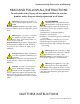
GFCI Wiring Diagram (North America 240V 60hZ)
WARNING:
The electrical circuit must be installed by an electrical con-
tractor and approved by a local building or electrical inspec-
tor. Failure to comply with state and local codes may result in fire or
personal injury and will be the sole responsibility of the spa owner.
Customer must provide a disconnect in the fixed wiring.
I
mproper installations present hazards which can result in per-
sonal injury or property damage and void the warranty on the spa.
!