Owner’s Guide and Installation Instructions Outdoor Domestic Mains Pressure Gas Storage Water Heater G270VE Series This water heater must be installed and serviced by a qualified person. Please leave this guide with the householder.
Warning: Upon completion of the installation and commissioning of the water heater, leave this guide with the householder or responsible officer. DO NOT leave this guide inside the cover of the water heater, as it may interfere with the safe operation of the water heater or ignite when the water heater is turned on. Patents This water heater may be protected by one or more patents or registered designs in the name of Aquamax Australia Pty Ltd.
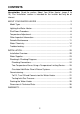
CONTENTS Householder: Read the section ‘About Your Water Heater’ (pages 3 to 19). The ‘Installation’ section is intended for the installer but may be of interest. ABOUT YOUR WATER HEATER ................................................................ 3 Model Type................................................................................................ 3 Lighting the Water Heater ......................................................................... 5 Shut Down Procedure ...........................
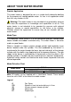
ABOUT YOUR WATER HEATER Product Application This water heater is designed for use in a single family domestic dwelling for the purpose of heating potable water. Its use in an application other than this may shorten its life. Warning: This water heater is only intended to be operated by persons who have the experience or knowledge and capabilities to do so. This water heater is not intended to be operated by persons with reduced physical, sensory or mental capabilities i.e. the infirm, or by children.
Mains Pressure Operation This water heater is designed to operate at mains pressure by connecting directly to the mains water supply. If the mains supply pressure in your area exceeds that shown in ‘Mains Water Supply’ on page 23, a pressure limiting valve must be fitted. The supply pressure should be greater than 350 kPa for true mains pressure operation to be achieved.
To minimise scalding, especially for those people in high scald risk categories i.e. young children, people with potentially incapacitating medical conditions, elderly people etc, this water heater must be installed in accordance with AS/NZS 3500.4. For early childhood centres, primary and secondary schools, nursing homes or similar facilities for young, aged, sick or disabled persons, please consult your local health authority for the correct temperature setting.
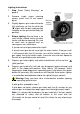
Lighting Instructions 1. Stop. Read ‘Safety Warnings’ on page 5. 2. Remove single screw retaining access panel and lift out access panel. 3. Slightly depress gas knob and rotate fully clockwise so that the white dot ‘ ‘ aligns with the gas knob position indicator on the gas control body (off position). 4. Before lighting: Ensure there is no smell of gas around vicinity of water heater and burner opening. Be sure to smell next to ground level as some gases can settle there.
7. Hold gas knob in depressed position for a further twenty (20) seconds and then release. 8. Depress gas knob slightly and rotate anticlockwise to the red line ‘l’ (ignition) position and hold in this position for five (5) seconds. 9. Release gas knob (gas knob will return to the red flame ‘ ’ (on) position automatically) and listen for burner noise. 10. If burner ignites, proceed to step 11. If burner fails to ignite, depress gas knob slightly and rotate gas knob to the white dot ‘ ‘ (off) position.
Shut Down Procedure To view the gas control components described in this procedure refer to the ‘Lighting Instructions’ diagram on page 6. 1. Remove front access panel by following step 2 of ‘Lighting Instructions’ on page 6. 2. Depress gas knob slightly and rotate gas knob clockwise so that the red star ‘ ’ aligns with the gas knob position indicator on the gas control body (pilot position). This setting will leave the pilot flame alight, however the main burner will not be able to ignite.
thermostat is fully automatic and the burner only operates when the water in the storage cylinder requires heating. There is no need to switch the water heater off when it is not in use, except when you are going away for an extended period. The temperature adjustment dial is on the front of the gas control located behind the front access panel of the water heater (refer to the diagram in ‘Lighting Instructions’ on page 6).
The Aquamax warranty may not cover faults if relief valves or other safety devices are tampered with or if the installation is not in accordance with these instructions. Warning: For continued safety of this water heater, it must be installed, operated and maintained in accordance with the Owner’s Guide and Installation Instructions. These instructions must be read in conjunction with all other instructions affixed to the appliance.
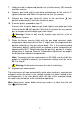
was to become inoperable for any reason. We recommend you seek advice from your plumber or specifier about your needs and building back up redundancy into your hot water supply system. Periodic Maintenance Minor Six Monthly Maintenance It is recommended minor maintenance be performed every six months by the dwelling occupant. Warning: Exercise care when operating easing levers as water discharged from the water heater may be of a very high temperature. Minor maintenance actions: 1.
Major Five (5) Year Service It is recommended a major five (5) year service be conducted on the water heater. Servicing must be performed by a qualified person. Phone Aquamax Service or their nearest Accredited Service Agent. Note: The five (5) year service and routine replacement of any components, such as the relief valve(s), are not included in the Aquamax warranty. A charge will be made for this work. Major five (5) year service actions: 1. Replace pressure temperature relief valve. 2.
Warning: Exercise care when operating easing lever as water discharged from the water heater may be of a very high temperature. Warning: Exercise care to avoid any splashing of water, as water discharged from the drain line will be hot. Stand clear of the drain line’s point of discharge when operating the valve’s lever. Danger: Failure to perform this procedure may result in the water heater storage cylinder failing.
The life of the storage cylinder may be extended by arranging a qualified person to periodically inspect the anode and replace if required. If the anode is not replaced during a five (5) year service (refer to ‘Major Five (5) Year Service’ on page 12) then the maximum time after installation when the anode should be replaced for this electric water heater is eight (8) years.
The Aquamax warranty will not cover resultant faults to the storage cylinder if this water heater is connected at anytime to a water supply where the TDS content of the water exceeds 600 mg/Litre. In locations where TDS approaches 600 mg/Litre, e.g. due to sediment, we strongly recommend fitting an appropriate filter to ensure water entering or in the water heater does not exceed this level at any time i.e. due to sediment build up.
Water Chemistry Levels Affecting Warranty The Aquamax warranty of this water heater will not cover resultant faults on components including the storage cylinder where water stored in the storage cylinder exceeds at any time any of the following levels: Total dissolved solids Total hardness Chloride Magnesium pH Calcium Sodium Iron 600 mg/Litre 200 mg/Litre 300 mg/Litre 10 mg/Litre 9.5 and not less than 6.
Troubleshooting Check the items below before making a service call. You will be charged for attending to any condition or fault that is not related to the manufacture or failure of a part. For warranty terms and conditions (refer to ‘Warranty’ on page 39). Not Enough Hot Water (Or No Hot Water) • Is a pilot flame present? Remove the front access panel and check that a pilot flame is present. If the pilot flame is not burning relight the heater by following the ‘Lighting Instructions’ on page 6.
Pressure Temperature Relief Valve Running • Normal Operation It is normal and desirable for the PTR valve to allow a small quantity of water to escape during the heating cycle, however there may be a problem if the valve continuously dribbles more than a bucket full of water in a normal 24 hr cycle. • Continuous dribble Try gently raising the easing lever on the relief valve for a few seconds (refer to ‘Pressure Temperature Relief Valve’ on page 12).
around the base of the water heater. This is quite normal, especially in winter months and the condensate will dry off as the water is heated. The water heater will drip water during the heating cycle. It is possible for several litres a day of condensation to discharge from the unit, especially in cool conditions. This water is not from the mains supply but is condensation from the atmosphere caused by the efficient operation of the water heater.
INSTALLATION Installation Overview This water heater must be installed by a qualified person in accordance with the installation instructions. The installation must comply with the requirements of AS/NZS 3500.4, AS 5601 or AS/NZS 5601.1, all local codes and regulatory authority requirements. Check to ensure the water heater is suitable for the gas type available (refer to the water heaters rating label). All packaging materials must be removed from the water heater prior to its installation.
It is a requirement of AS 5601 and AS/NZS 5601.1 that the water heater is secured to a wall. A wall bracket is supplied with the water heater for this purpose. The top of the unit is to be secured to the wall using the wall bracket and masonry anchor provided (or other suitable fastener). Refer to ‘Wall Bracket Installation’ on page 22. Note: Damage to the storage cylinder caused by incorrect installation is not covered by warranty.
Examples a, b & c from previous table Wall Bracket Installation It is a requirement of AS 5601 and AS/NZS 5601.1 that water heater is secured to a wall. The top of the water heater is to be secured to the wall using the wall bracket and M6.5 masonry anchor provided with the water heater (or other suitable fastener). It is necessary to fix the bracket to the wall after positioning the water heater but prior to making the water and gas connections. To install the wall bracket: 1. Position water heater. 2.
Safe Tray Where damage to property can occur in the event of the water heater leaking, the water heater must be installed in a safe tray. Construction, installation and draining of a safe tray must comply with AS/NZS 3500.4 and all local codes and regulatory authority requirements. AS/NZS 3500.4 also has particular requirements when a safe tray must be installed.
including the water heater. Care must be taken to avoid air locks. The cold water supply line to the water heater must be adequately sized and fitted with an approved full flow gate valve or ball valve and non return valve. Water Supply Chemistry Bad water can have a detrimental effect on water heater operation, components and life expectancy and may affect warranty. Refer to ‘Water Chemistry’ on page 14 for more information. Also refer to ‘Spring, Dam, Bore & River Water Supplies’ on page 16.
Natural Gas Models: Remove yellow warning label from gas control after connecting gas supply line. Propane Gas Models: A gas regulator is supplied with the water heater and must be installed externally between the gas isolation valve and jacket of the water heater. Refer to gas flow directional arrow on regulator body to ensure it is installed in the correct orientation. The regulator has been factory preset to obtain a burner pressure of approximately 2.7kPa.
Expansion Control Valve In some areas, local regulations may make it mandatory to install an expansion control valve (ECV) in the cold water line to the water heater. Refer to ‘Scaling Water’ on page 16. The ECV must always be installed after the non return valve and be the last valve installed prior to the water heater (refer to the ‘Cold Water Supply Plumbing Arrangement’ diagram on page 25). A copper drain line must be fitted to the ECV (refer to ‘Relief Valve Drain(s)’ on page 26).
additional bends. Where the distance to the point of final discharge exceeds this length, the drain line can discharge into a tundish. Subject to local regulatory authority approval, the drain lines from the ECV and PTR valve from an individual water heater may be interconnected. The outlet of a drain line must be in such a position that flow out of the pipe can be easily seen, but arranged so discharge will not cause injury, damage or nuisance.
cylinder is damaged as a result of installing a Flashing Kit, any resultant faults will not be covered by the Aquamax warranty. Two Temperature Zones Using a Temperature Limiting Device This water heater can deliver water at temperatures which can cause scalding. It is necessary and we recommend that a temperature limiting device be fitted between the water heater and the hot water outlets in any ablution area such as a bathroom or ensuite, to reduce the risk of scalding.
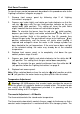
Two Temperature Zone Plumbing Diagram Circulated Hot Water Flow & Return Systems For circulated hot water flow and return systems, a temperature limiting device can only be installed on a dead leg which branches off the circulated hot water flow and return pipe.
Circulated Hot Water Flow & Return Plumbing Diagram 30
Commissioning To Fill, Turn ON and Commission the Water Heater Warning: The pilot or burner must not be lit until the water heater is filled with water. 1. Open all hot water taps in premises including shower(s). 2. Fully open cold water isolation valve on cold water line to water heater. This will purge air from hot water plumbing lines via taps opened in step 1. 3. Close each hot water tap after all air is purged (when air is purged water will run freely without air bubbles or spluttering). 4.
Leave this guide with the householder or responsible officer upon completion of the installation and after commissioning. Warning: DO NOT leave this guide inside the water heater as it may interfere with the safe operation of the water heater or ignite when the water heater is turned on. To Turn OFF the Water Heater Sometimes it is necessary to turn off the water heater after installation and commissioning. This may be required on a building site or where the premises are vacant.
1. Ensure all other gas appliances in the premises are operating (burners alight). 2. Ensure water heater is turned off and gas control is completely shut down (refer to ‘Shut Down Procedure’ on page 8). 3. Remove screw from inlet gas pressure test point on gas control and attach manometer hose to test point. 4. Light the water heater and ensure burner is operating (refer to ‘Lighting Instructions’ on page 6). 5. Take manometer reading with burner operating. 6.
5. Take manometer reading with burner operating. If reading is 1.0 kPa for natural gas models or 2.7 kPa (±5% tolerance) for propane gas models, the burner gas pressure is correct. Proceed directly to step 7. If reading is not 1.0 kPa for natural gas models or 2.7 kPa (±5% tolerance) for propane gas models, the burner gas pressure will require adjusting in which case proceed to step 6a for natural gas models or step 6b for propane gas models. 6. a. Natural Gas Models i.
Draining the Water Heater Warning: Water discharged from the water heater during this procedure may be of a very high temperature. Wear personal protective equipment (PPE) to reduce the risk of scalding. To drain the water heater: 1. Ensure water heater is turned off and gas control is completely shut down (refer to ‘Shut Down Procedure’ on page 8). 2. Close cold water isolation valve on cold water line to water heater. 3. Close all hot water taps in premises. 4.
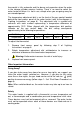
Dimensions & Technical Data G270VE Model – Without Mixing Valve APPROVALS: This unit complies with AS 3498 WaterMark Licence No.
This page is intentionally blank 37
This page is intentionally blank 38
WARRANTY AQUAMAX GAS DOMESTIC MAINS PRESSURE WATER STORAGE HEATER WARRANTY – AUSTRALIA ONLY1. THE AQUAMAX WARRANTY - GENERAL 1.1 This warranty is given by Aquamax Australia Pty Limited, ABN 37 138 189 689 of 463-467 Warrigal Road, Moorabbin Victoria. 1.2 Aquamax offer a trained and qualified service network who will repair or replace components at the address of the water heater subject to the terms of the Aquamax warranty.
2.4 Where the water heater is installed outside the boundaries of a metropolitan area as defined by Aquamax or further than 25 km from either a regional Aquamax branch office or an Accredited Aquamax Service Agent’s office, the cost of transport, insurance and travelling between the nearest branch office or Aquamax Accredited Service Agent’s office and the installed site shall be the owner’s responsibility. 2.
2.8 Subject to any statutory provisions to the contrary, this warranty excludes any and all claims for damage to furniture, carpet, walls, foundations or any other consequential loss either directly or indirectly due to leakage from the water heater, or due to leakage from fittings and/or pipe work of metal, plastic or other materials caused by water temperature, workmanship or other modes of failure. 2.
4. ENTITLEMENT TO CLAIM UNDER THIS WARRANTY 4.1 To be entitled to make a claim under this warranty, you need to: a. Be the owner of the water heater or have consent of the owner to act on their behalf. b. Contact Aquamax Service without undue delay after detection of the defect and, in any event, within the applicable warranty period. 4.2 You are not entitled to make a claim under this warranty if your water heater: a. Does not have its original serial numbers or rating label. b.
INSTALLER INFORMATION DEAR INSTALLER, Please provide the following information upon completion of the installation. This information should be provided to Aquamax to assist the customer in the event that a claim is made under the Aquamax warranty. Plumber (Name & Company): Plumber’s licence number: Compliance Certificate: (if applicable in your state) Installation date: Model & serial number: Water Heater date of manufacture: AQUAMAX AUSTRALIA PTY. LTD ABN 37 138 189 689 www.aquamax.com.