VV Model 33011-3/33021-3/33031-3 32011-3/32021-3/32011-1/32021-1 32031-3/32031-1 30011-3/30021-3/30031-3 OWNER’S MANUAL SUBMERSIBLE SUMP PUMP Piggyback tethered float Piggyback vertical float switch switch Questions, problems, missing parts? Before returning to the store call AQUAPRO Customer Service 8 a.m. - 5 p.m., EST, Monday-Friday 1-844-242-2475 © 2015CopyrightGP EnterprisesCo .
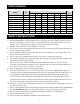
PERFORMANCE GPH of Water @ Total Feet Of Lift 0 ft. 5 ft. 10 ft. 15 ft. 20 ft. 25 ft. Max. Lift 1/4 3450 3200 2800 2100 1500 200 26 ft. 33021-3 1/3 3600 3400 3000 2500 1900 1000 28 ft. 33031-3 1/2 4100 3800 3500 2900 2300 1600 29 ft. 32011-3/32011-1 1/3 3800 3400 3000 2500 1800 32021-3/32021-1 1/2 4300 3900 3500 3100 2500 1700 30 ft. 32031-3/32031-1 1/2 3900 3700 3400 3100 2700 2200 37 ft.
15. Secure the pump to a solid base. This will aid in keeping the pump in a vertical orientation. This is critical in keeping the pump operating at maximum efficiency. It will also help prevent the pump from clogging resulting in premature failure. 16. Periodically inspect the pump and system components to ensure the pump suction screen is free of mud, sand, and debris. Disconnect the pump from the power supply before inspecting. 17.
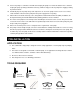
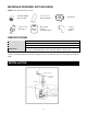
MATERIALS REQUIRED (NOT INCLUDED) NOTE: Parts shown below not to scale. Threaded Adapter (Pipe to Pump) 1-1/4’’ or 1-1/2’’ ABS or PVC Pipe Thread Tape 1-1/4” or 1-1/2” check valve ABS or PVC Cement (to match the pipe) 1-1/4” or 1-1/2”90° Elbow SPECIFICATIONS Power supply Liquid temp. range Discharge size Sump basin 115V, 60 HZ., 15 Amp Circuit 35°F to 77°F (1°- 25°C) 1-1/2 in. FNPT or 1-1/4 in. FNPT (with adaptor) Min. 14 in. (356 mm) diameter, 18 in. (457 mm) depth for tethered switch Min. 10 in.
1. Install the pump in sump pit with minimum diameter of 10 in. (254 mm) for models equipped with vertical switches and 14 in. (356 mm) for tethered float switch models. The sump depth should be 14 in. (356 mm) for vertically switched models and 18 in. (457 mm) for tethered models. Construct the sump pit of tile, concrete, steel or plastic. Check local codes for approved materials and for proper installation. 2. Install the pump in a pit so that the switch operating mechanism has maximum possible clearance.
10. Check the pump operation by filling the sump with water and observing pump operation through one complete cycle. CAUTION : Risk of flooding. Can cause personal injury and/or property damage. Failure to make this operational check may lead to improper operation, premature failure, and flooding. OPERATION WARNING: Risk of electric shock. Can shock, burn or kill. Do not handle a pump or pump motor with wet hands or when standing on a wet or damp surface, or in water. 1.
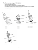
To clean a pump clogged with debris: Unplug the pump from electrical power. Unscrew the stainless screws, and remove the volute/bottom seal plate. Use a flathead screwdriver to hold the shaft, then turn the impeller counterclockwise to release the impeller. Remove debris from around the shaft and on/under the impeller. Reassemble the pump.
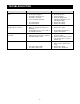
TROUBLESHOOTING Problem The pump does not start or run. The pump operates but pumps little or no water. The pump starts and stops too often. The pump will not shut off. Possible Cause 1. The fuse is blown. 2. The breaker is tripped. 3. The plug is disconnected. 4. The plug is corroded. 5. There is thermal overload. 6. 7. 1. 2. The switch failed. The motor failed. The screen is blocked. Debris is caught in the impeller or discharge. 3. The impeller is loose on the shaft or the impeller is broken. 1.
WARRANTY Limited Warranty WHAT THIS WARRANTY COVERS When used and maintained in normal use and in accordance with the Owner’s Manual, your AQUAPRO product is warranted against original defects in material and workmanship for at least one year (warranty varies depending on model; see box for specific warranty information) from the date of purchase (the “Warranty Period”).
Model 33011-3/33021-3/33031-3 32011-3/32021-3/32011-1/32021-1 32031-3/32031-1 30011-3/30021-3/30031-3 MANUAL DEL USUARIO BOMBA DE TANQUE SUMERGIBLE Flotador de Anclado a Flotador de Anclado Cuestasswitch Verticalswitch ¿Preguntas, problemas, piezas que faltan? Antes de devolverla a la tienda, llame a Servicio al Cliente de 8:00 AM a 5:00 pm EST de Lunes a Viernes.
RENDIMIENTO Modelo HP Galones Por Hora de Agua por Total de Pies con Manguera de ¾ de Pulgada 0 pi. 5 pi. 10 pi. 15 pi. 20 pi. 25 pi. 33011-3 1/4 3450 3200 2800 2100 1500 200 26 pi. 33021-3 1/3 3600 3400 3000 2500 1900 1000 28 pi. 1600 29 pi. Alzamiento Máximo 33031-3 1/2 4100 3800 3500 2900 2300 32011-3/32011-1 1/3 3800 3400 3000 2500 1800 32021-3/32021-1 1/2 4300 3900 3500 3100 2500 1700 30pi. 32031-3/32031-1 1/2 3900 3700 3400 3100 2700 2200 37 pi.
. Asegúrese de que el circuito eléctrico a la bomba este protegido por un fusible de 15 amperios o un cortacircuitos. 13. No levante la bomba por el cable eléctrico. 14. Conozca de la bomba las aplicaciones, las limitaciones y los peligros potenciales. 15. Asegúrese de que la bomba esté en una base sólida para mantenerla vertical por encima de barro y tierra durante el funcionamiento para maximizar la eficiencia de la bomba y prevenir que se tape o una falla prematura. 16.
MATERIALES NECESARIOS (NO INCLUIDOS) NOTA: Manguera y equipo de manguera no están mostrados a escala. Adaptador Enroscado (Del tubo a la Bomba) Válvula de Retención de 1 ¼ o 1 ½ pulgadas Tubería de ABS o PVC de 1¼ o 1½ pulgadas Cemento de ABS o PVC (Que concuerde con la tubería) CintaSellante Tubo de Codo de 90o de 1 ¼ o 1 ½ pulgadas ESPECIFICACIÓNES Fuente de Alimentación Alcance de Temperatura de Líquidos Tamaño del Desagüe Deposito del Pozo 115 Volteos, 60 HZ.
1. Instale la bomba en la fosa o pozo con un diámetro mínimo de 10 pulgadas (254 mm) para modelos equipados con interruptores verticales y con 14 pulgadas (356 mm) para modelos con el interruptor a cuestas. La profundidad del pozo o fosa tiene que ser de 14 pulgadas (356 mm) para modelos con interruptores verticales y con 18 pulgadas (457 mm) para modelos con el interruptor a cuestas. Construya la fosa o pozo para la bomba de azulejo, cemento, acero o plástico.
8. Si la línea de desagüe de la bomba está expuesta a la atmosfera bajo cero, una porción de línea expuesta tiene que ser instalada para que cualquier agua restante en el tubo se drene por medio de gravedad. Si usted no hace esto puede causar que el agua que quede atrapada en el desagüe se congele, lo que puede resultar en el daño de la bomba. 9. Después que la tubería y la válvula de retención hayan sido instaladas, la unidad estará lista para operar. 10.
Como limpiar una bomba bloqueada por deshechos: Desenchufe la bomba de la corriente eléctrica Desatornille los tornillos de acero inoxidable y remueva la placa de la voluta en espiral. Utilice un desatornillador de punta plana para sujetar el eje. Después dé vuelta al impulsor hacia la izquierda para liberar el impulsor. Remueva los deshechos que se encuentren alrededor del eje y alrededor o debajo del impulsor. Vuelva a montar la bomba.
RESOLUCIÓN DE PROBLEMAS Problema La bomba no prende o no comienza La bomba funciona pero no desaloja agua o desaloja muy poca agua La bomba comienza y se para muy seguido La bomba no se apaga Causas Probables 1. El fusible está fundido 2. El interruptor tiene falla. 3. El cable de conexión esta desenchufado. 4. El cable de conexión esta corroído. 5. Hay una sobrecarga térmica. 6. 7. 1. 2. En interruptor tiene una falla. El motor está descompuesto. El protector está bloqueado.
GARANTÍA Garantía Limitada LO QUE CUBRE ESTA GARANTÍA Cuando se usa y se mantiene de forma normal y de acuerdo con el manual del propietario, su producto AQUAPRO está garantizado contra defectos de materiales y de mano de obra durante al menos un año (la garantía varía según el modelo; revise la caja para obtener información específica sobre la garantía) a partir de la fecha de comprar (el "Período de Garantía").