
Use and Care Manual

5
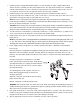
1. Install the pump in sump pit with minimum diameter of 10 in. (254 mm) for models equipped with vertical
switches and 14 in. (356 mm) for tethered float switch models. The sump depth should be 14 in. (356 mm) for
vertically switched models and 18 in. (457 mm) for tethered models. Construct the sump pit of tile, concrete,
steel or plastic. Check local codes for approved materials and for proper installation.
2. Install the pump in a pit so that the switch operating mechanism has maximum possible clearance.
3. The pump should not be installed on clay, earth or sand surfaces. Clean the sump pit of small stones and
gravel which could clog the pump. Keep the pump inlet screen clear.
NOTE: Do not use ordinary pipe joint compound on plastic pipe. Pipe joint compound can attack plastics.
4. Install discharge plumbing. Use rigid plastic pipe and wrap threads with PTFE pipe thread sealant tape. Screw
pipe into the pump hand tight plus 1-1/2 turns.
CAUTION: Risk of flooding. Can cause personal injury and/or property damage. If a flexible discharge hose is
used, make sure the pump is secured in the sump to prevent movement. Failure to secure the pump may allow
pump movement, switch interference and prevent the pump from starting or stopping.
5. To reduce motor noise and vibrations, a short length of rubber hose (1-7/8 in. (47.6 mm) I.D., e.g. radiator hose)
can be connected into the discharge line near the pump using suitable clamps.
6. Install an in-line check valve or an in-pump check valve to prevent flow backwards through the pump when the
pump shuts off.
NOTE: If your check valve is not equipped with an air bleed hole to prevent air locking the pump, drill a 1/8
in. (3.2 mm) hole in the discharge pipe just above where the discharge pipe screws into the pump
discharge. Be sure the hole is below the waterline and the check valve to prevent air locks.
7. Power Supply: Pump is designed for 115 V, 60 Hz, operation and requires a minimum 15 amp individual
branch circuit.
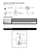
Plug the pump power cord plug into the piggyback switch plug outlet, and then plug the switch plug into a 115V
GFCI power outlet for automatic operation. The pump will start operating if the float switch moves over the
pump top. The water will be pumped out. When the water lowers to certain level, the float switch will turns off
the pump.
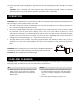
Or plug the pump power cord plug into a 115V GFCI
power outlet directly for manual operation. Pump will start
operating immediately once it plug to the GFCI and drain
water out, when the water moved out, you must unplug
the pump immediately.
The following picture shows a typical connection for
pumps with the piggy-back plug, for manual and
automatic operations.
Automatic - Plug float cord into GFCI outlet, then plug
pump cord into float cord.
Manual - Plug pump cord directly into GFI outlet.
WARNING: Risk of electric shock. Can shock, burn or kill. Pump should always be electrically grounded to a
suitable electrical ground such as a grounded water pipe or a properly grounded metallic raceway, or ground
wire system. Do not cut off the round ground pin.
8. If the pump discharge line is exposed to outside subfreezing atmosphere, a portion of line exposed must be
installed so any water remaining in the pipe will drain to the outfall by gravity. Failure to do this can cause water
trapped in the discharge to freeze which could result in damage to the pump.
9. After the piping and check valve have been installed, the unit is ready for operation.