ITEM #0247101 0247458 TUB AND SHOWER FAUCET AquaSource® is a registered trademark of LF, LLC. All Rights Reserved. MODEL #873-W3701 873-W3727H2 Francias / Español p. 13 ATTACH YOUR RECEIPT HERE Serial Number ____________ Purchase Date ____________ Questions, problems, missing parts? Before returning to your retailer, call our customer service department at 1-866-417-7564, 8 a.m. - 8 p.m., EST, Monday - Friday. Lowes.
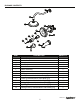
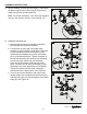
PACKAGE CONTENTS A B C D E L K G M J I N H F PART A B C D E F G H I J K L M N DESCRIPTION Shower Flange Shower Arm Showerhead Valve Body Escutcheon Handle Assembly Plug Tub Spout Screw (Preassembled to Valve Body (D)) Inverter (Preassembled to Valve Body (D)) Bonnet (Preassembled to Valve Body (D)) Cartridge (Preassembled to Valve Body (D)) Stop Ring (Preassembled to Valve Body (D)) Cartridge Stem (Preassembled to Valve Body (D)) QUANTITY 1 1 1 1 1 1 1 1 1 1 1 1 1 1 Lowes.
SAFETY INFORMATION Please read and understand this entire manual before attempting to assemble, operate, or install the product. WARNING: Follow the installation instructions carefully. Proper installation is the installer’s responsibility. Failure to follow correct installation procedures can result in the faucet being loose, which can result in serious injury. CAUTION: Check local building codes before beginning installation to ensure compliance.
ASSEMBLY INSTRUCTIONS 1. Prepare the bath area for installation: 1 a. Shut off the water supply to the tub and shower. Note: This may require shutting off the main water supply to your home. b. Verify that the hole sizes and positions in the wall are correct. Here are the recommended component measurements: 1 1/4 in. Dia 30 in. Shower Only 6 in. Dia – Shower and Spout Outlet Hole: 1-1/4 in. diameter – Valve Access Hole: 6 in. diameter – Recommended Valve Depth to Finished Wall: 2 in. min. to 2-1/2 in.
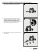
ASSEMBLY INSTRUCTIONS 3. Before installing, unscrew the two screws (1) that attach the plastic cap (2) to the valve body (D). Remove the plastic cap (2) from the valve body (D). 3 2 1 Note: For proper installation, valve body (D) should be turned in the direction with the valve marked “UP”. D 4. Install the valve body (D): 4a 4 a. Wrap thread sealant (not included) around the pipe threads in a clockwise direction. 1 b.
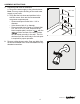
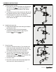
ASSEMBLY INSTRUCTIONS 5. Install the shower arm (B): 5 a. Insert the long end of the shower arm (B) through the shower arm (A) and wrap plumber’s tape (not included) to both sides of the shower arm (B). A B b. Thread the long end of the shower arm (B) into the pipe elbow inside the wall in a clockwise direction. c. Carefully tighten the shower arm (B) with a wrench. Do not overtighten as it could do damage to the shower arm (B). 6. Install the tub spout (H): 6 a.
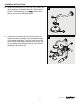
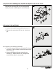
ASSEMBLY INSTRUCTIONS 8. Install the showerhead (C) to the end of the shower arm (B) by twisting in a clockwise direction. Tighten with a wrench. To avoid damage to the place a cloth between the wrench and showerhead. 8 B C 9. Position the escutcheon (E) over the valve body (D). Attach the handle assembly (F) by threading the base of the handle assembly (F) onto the valve stem of the valve body (D) and twisting clockwise until secure.
ADJUSTING THE TEMPERATURE LIMITER AND WATER FLOW ON THE VALVE The limiter on the valve can be set to allow partial or full access to hot water by limiting how far the handle can be turned to the hot side of the valve. The limiter is typically set at the factory to allow only warm water to pass through the valve. Follow the directions in this section if you wish to adjust the amount of hot water that is allowed through the valve. 1.
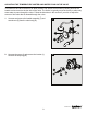
ADJUSTING THE TEMPERATURE LIMITER AND WATER FLOW ON THE VALVE 3. Slowly turn the cartridge stem (N) counterclockwise to adjust the desired maximum water temperature. 3 N 4. 5. Reinstall the stop ring (M) and readjust the teeth engagement position so that the stem cannot move beyond the adjusted point. Optionally, you can completely remove the stop ring (M) to allow the maximum amount of hot water through the valve. This does not affect the performance of the valve.
ADJUSTING THE TEMPERATURE LIMITER AND WATER FLOW ON THE VALVE 6. Replace the escutcheon (E) and handle assembly (F) 6 back onto the valve body (D). Do not overtighten the handle (F) as this could damage the escutcheon (E). D E F REPLACING THE CARTRIDGE 1a. Remove the old cartridge: 1a a. Unscrew the handle assembly (F) and remove it. b. Remove the escutcheon (E) from the valve body (D). D E F 1b. Remove the old cartridge (continued): 1b a. Turn off the stops (1) on the valve body (D).
CARE AND MAINTENANCE Clean carefully by gently wiping with a grit-free damp cloth. Use only mild soap with water. Never use acids, harsh chemicals, or abrasive detergents to clean the surface. TROUBLESHOOTING PROBLEM POSSIBLE CAUSE CORRECTIVE ACTION There is a leak from under the handle. The cartridge is damaged. Remove the handle and replace the cartridge. There is an inconsistent waterpattern. The showerhead is dirty or has accumulated debris. The spout/ showerhead has a leak.
REPLACEMENT PARTS LIST For replacement parts, call our customer service department at 1-866-417-7564, 8 a.m. - 8 p.m., EST, Monday - Friday. PART DESCRIPTION PART # 1 Handle RP13282* Assembly 2 Escutcheon RP80350* 3 Screw RP50155 4 Inverter RP70040 5 Cartridge RP20006 6 Plug RP70392 7 Shower Flange RP38160* 8 Shower Arm RP38161* 9 Showerhead RP38177* 10 Tub Spout RP33055* * Available in Chrome Finish and Oil Rubbed Bronze Finish.