I N S TA L L AT I O N A N D O P E R AT I N G I N S T R U C T I O N S F O R A U T O M AT I C I N S TA N TA N E O U S T Y P E WAT E R H E AT E R S F O R U S E W I T H N AT U R A L A N D L I Q U E F I E D P E T R O L E U M G A S MODEL 80 VP AND MODEL 80VPS Suitable for water (potable) heating and space heating WARNING: If the information in this manual is not followed exactly, a fire or explosion may result causing property damage, personal injury or death.
TABLE OF CONTENTS Specifications .............................................................................. Page Rules for Safe Operation ............................................................. Page General Overview of Aquastar .................................................... Page Locating the Heater for Safe Proper Combustion........................ Page Installation ...................................................................................
AquaStar 80 VP and 80 VP "S" Specifications: Gas input..................................max: 77,500 Btu min: 25,000 Btu Water Connection........................1/2" sweat fitting H x W x D..........................................27" x 12" x 9" Vent.......................................................................4" Gas Connection...........................3/4" NPT thread Min. Water Pressure....................................15 Psi Max. Water Pressure................................
CAUTION: RULES FOR SAFE OPERATION If you are using the AquaStar for combined space heating and potable water heating (see schematic diagram below), all piping and other components connected to the system must be suitable for potable water, (b) toxic chemicals such as those commonly used for boiler treatment to prevent corrosion and freezing must not be introduced into the system, and (c) if the space heating requires water temperatures higher than those required for domestic, potable water, a mixing valve
RULES FOR SAFE OPERATION 6. Keep water heater area clear and free from combustibles and flammable liquids. Do not locate the heater over any material which might burn, such as carpet. 1. You should follow these instructions when you install your heater. In the United States: The installation must conform with local codes or, in the absence of local codes, the National Fuel Gas Code ANSI Z223.1/ NFPA 54. In Canada: The installation should conform with CGA B149.
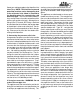
Fig. 2 Parts of AquaStar 80 X A W B V C E D T F S G R J I A. hanging frame and back support Y K H I. Z L hot water outlet M P T. pilot J. thermostat adjustment screw V. overheat shut off sensor K. gas inlet W. draft hood L. manual gas valve X. rating plate-serial # & gas type, etc. E. burners M. cold water inlet screen Y. incandescent particles tray F. burner manifold P. pilot starting button G. gas pressure testing nipple R. water valve venturi piston Z.
LOCATING YOUR HEATER FOR SAFE PROPER COMBUSTION Carefully select the location of your new heater. For your safety and for proper heater operation, you must provide an abundant supply of combustion air and install a proper vent. The heater may still operate even when improperly installed. However, an improper installation will be less efficient and may damage the heater. Improper installation can even result in human sickness or death due to oxygen deprivation and carbon monoxide poisoning.
. For alcove installation, maintain the following heater. Use the adhesive tape which is included minimum clearances from all construction for ser- in the package to stick the pattern to the wall. Keep in mind that the heater needs to have cervicing and proper operations: tain minimum clearances (See paragraph 7 on Alcove Closet this page), and that the heater must be level. Drill A. Top 6 inches 12 inches four holes into the wall at the studs (16 inches on B.
Fig. 3 To Disconnect Heater From Wall Hanging Strip 3. Connecting the Gas Line In the United States: The installation must conform with local codes or, in the absence of local codes, the National Fuel Gas Code ANSI Z223. 1/NFPA 54. In Canada: The installation should conform with CGA B149 INSTALLATION CODES and/or local installation codes. IMPORTANT An appliance gas pressure regulator has been supplied with this unit. This regulator must be installed on the gas line within 6 feet of the heater.
Sweat your cold water pipe to the AquaStar inlet elbow fitting. NOTE: The inlet filter screen and water flow restrictor can be damaged by heat if the cold water inlet elbow is attached to the AquaStar when it is sweated to the cold water inlet pipe. The inlet and outlet elbow fittings seal by means of a union connection with a washer type gasket at the joint.
FOR YOUR SAFETY READ BEFORE LIGHTING WARNING: If you do not follow these instructions exactly, a fire or explosion may result causing property damage, personal injury or loss of life. A. B. This appliance has a pilot which must be lighted by hand. When lighting the pilot, follow these instructions exactly. BEFORE LIGHTING smell all around the appliance area for gas. Be sure to smell next the floor because some gas is heavier than air and will settle on the floor.
SETTING THE WATER TEMPERATURE The AquaStar 80 water heater contains a flow restrictor set at 3 1/4 gpm. Its purpose is to assure that the hot water temperature will always be within a comfortable range regardless of how high one may turn on the hot water faucet or how many faucets may be turned on. Your AquaStar model 80 also has an automatic thermostatic control with a manual temperature setting (Fig. 2 letter H p. 6).
valve discharges by itself, a problem exists and Wash the stainless steel burners if they are dirty. service is required. This could be due to a de- Burners can be detached from the heater by refective relief valve or to overheating. moving the pilot tube and the thermocouple assembly and disconnecting the Energy-Cut-Off. Pilot Flame: The pilot flame should burn with (Do not lose the retaining clip) The burners a clean sharp blue flame and should resemble are secured to the main frame by two screws on Fig.
Mineral Scale Buildup:AquaStars, when operated at high temperatures or in hard water areas, may need periodic descaling. To check the inside of the heat exchanger for scaling, remove the heat exchanger by first removing the thermostat sensing element (B), page 6. If you note mineral buildup, flush with a descaling solution. Consult your dealer or call CEC for instructions. TROUBLE SHOOTING 2. In-line AquaStar gas regulator jammed (usually with LP gas) Replace or unjam the regulator.
3. Poor circuit connections at the ECO (Energy Cut-Off) Oxidation or looseness of the ECO screw connections can result in millivolt current loss through the thermocouple safety circuit. Clean terminals with very fine sand paper or an eraser and retighten terminal screws. (See letter V in Fig 2, page 6). 4. Pilot orifice may not be correct for your type of gas. Pilot orifice is stamped: #18 for LP and #35 for NG. 5.
Attach a multimeter lead on the thermocouple copper tubing below the head, and attach the other meter lead on the ends of both the wires. Light the pilot and take a reading on the meter. If it reads less than 24 mv, replace the thermocouple. If the reading is 24 mv or over, the thermocouple is good. To test the electromagnet, reconnect the thermocouple and take another reading. The reading should drop to about 14 mv. If it does not, replace the electromagnet.
2. Water flow through the heater is higher than the capacity of the AquaStar to heat it If the AquaStar flow restrictor has been removed, the flow through the heater might be higher than its capacity to heat it. Reduce the flow to a range within which the heater can maintain temperature. See flow chart on Page 18.
2. Unbalanced pressure in water lines The added restriction caused by theAquaStar in the hot water system can result in uneven pressures between the cold and the hot. In such cases when mixing cold water at the tap, the lower hot water pressure may be overpowered by a much higher cold water presure, which may cause the 6. Parts in water flow valve (#34343) are AquaStar burners to shut down.
CLEANING THE PILOT ASSEMBLY AquaStar models 80/125/170 A. Removing Pilot 1.Hold Gas Pilot Filter Housing in place with one wrench. 2. Unscrew Pilot Tube nut with second wrench. 3.Save the little white Gasket for reassembly. 4. Pivot the tube to the left (loosen base fitting if needed). 5. Remove upper “hairpin” retaining clip. 6. Pull Pilot Assembly downward out of bracket. B. Cleaning the Pilot 1. Separate the chrome Pilot Burner from the brass Gas Pilot Filter Housing.
CALIBRATION AND THERMOSTAT TEST SYMPTOMS OF A DEFECTIVE OR IMPROPERLY CALIBRATED THERMOSTAT: The hot water is too hot. Usually this results in the heater shutting down on overheat safety. The pilot frequently goes out and needs to be relighted. PROCEDURE TO CALIBRATE THERMOSTAT (See diagram for correct location of screw to recalibrate) 1.Turn calibration screw in clockwise all the way, compressing the spring. 2.Back out screw 1 1/2 full turns.
PROCEDURE FOR REPLACING A THERMOSTAT TO REMOVE THERMOSTAT: A. Your replacement thermostat comes as part of a kit. The kit includes additional replacement components to ensure a successful installation. When removing the old thermostat be certain to remove all its components ("O" Ring, and Steel Wedge) prior to installing the replacement thermostat. 1. Shut off gas to the heater by turning the handle on the main gas valve. 2.
DESCRIPTION OF OPERATION OF AQUASTAR 80/125 MODELS WATER PATH The gas shut-off safety devices are integrated with the pilot light. An Electro-Magnet in the Gas Valve ensures that gas flows to the burner only when there is a pilot light to ignite it. The Pilot Knob (#15) shuts gas off to the burners while you light the pilot. You must hold the Pilot Knob in at the single flame position long enough for it to heat the Thermocouple (#12).
DIAGRAMATIC LAYOUT 1. 2. 3. 4. 5. 6. HEAT EXCHANGER BURNERS WATER FLOW RESTRICTOR FLOW IGNITION DEVICE (LPG ONLY) THERMOSTATIC GAS FLOW MODULATOR GAS FLOW VALVE (THERMOSTATIC CONTROLLED) 7. GAS FLOW VALVE (WATER FLOW CONTROLLED) 8. COLD WATER INLET AND BUILT IN FLOW CONTROL (REMOVABLE) 9. 10. 11. 12. 13. PILOT LIGHT PILOT LIGHT ORIFICE PILOT LIGHT GAS FILTER THERMOCOUPLE ELECTROMAGNET GAS FLOW SHUT-OFF VALVE 14. MANUAL GAS FLOW SHUT-OFF VALVE 15. PILOT STARTER KNOB 16.
HOUSING COMPONENTS DIAGRAM AQUASTAR 80 38798 38799 SPARE PARTS LIST 38798 - RIGHT SIDE PANEL 38799 - LEFT SIDE PANEL 22527 - TEMPERATURE SELECTOR KNOB 23617 - PANEL RETAINING SCREW 28329 - PILOT STARTER KNOB 24 36540 - FRONT PANEL 33993 - INCANDESCENT PARTICLE TRAY
INTERIOR COMPONENTS DIAGRAM AQUASTAR 80 SPARE PARTS LIST 00839 - PILOT WASHER 00869 - RETAINING NUT FOR GAS INLET FITTING 00910 - RETAINING NUT FOR COLD INLET AND HOT WATER OUTLET 02147 - NG GAS PILOT INJECTOR 02434 - LP GAS PILOT INJECTOR 05964 - GAS FITTING WASHER 08565 - BURNER ASSEMBLY 20887 - THERMOCOUPLE 22040 - THERMOSTAT SENSING ELEMENT RETAINING SCREW 22045 - BURNER MANIFOLD RETAINING SCREW 22058 - THERMOCOUPLE RETAINING CLIP 22062 - WASHER 22349 - SCREW 23617 25687 25776 25779 27126 29596 29910
VALVE ASSEMBLY COMPONENTS DIAGRAM AQUASTAR 80 37613 37614 SPARE PARTS LIST 02071 02103 20596 20597 20772 20775 20799 20883 20897 - 20971 21104 21107 21108 21135 - MANUAL GAS VALVE GASKET INJECTORS - NG WATER VALVE COVER WATER VALVE HOUSING CORK GASKET REGULATOR COVER CENTERING TUBE ELECTROMAGNET WITH WASHER THERMOCOUPLE PUSH ROD COVER CORK WASHER ELECTROMAGNET RETAINING COVER NG MODULATING THERMOSTATIC VALVE ASSEMBLY CONNECTOR WATER VALVE PUSH ROD NG VALVE HOUSING LP GAS THERMOSTATIC MODULATING VALVE
INST ALLA TION CHECKLIST INSTALLA ALLATION Gas Line Size* Natural Gas Nominal Iron Pipe Size* 1/2" 3/4" 1" Model 80 125 170 25" NR NR 100' 40' 25' 150' 125' 80' Liquid Propane Semi-rigid Tubing Model 80 125 1/2" 15' NR 5/8" 50' 20' 3/4" 100' 50' 7/8" 100' 170 NR NR 35' 70' *Flex tubing greatly reduces capacity and, therefore, is not recommended. Minimum Vent Size* and Height Model Min. Diameter Min.
GENERAL Controlled Energy Corporation (CEC) will furnish a replacement heat exchanger and will furnish a replacement of any other part, which fails in normal use and service within the applicable periods specified below, in accordance with the terms of this warranty. The CEC replacement will be warranted for the unexpired portion of the original warranty. This warranty will be valid only for water heaters in the possession of the original consumer purchaser as recorded on the warranty card.