
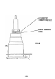
System information


BEFORE THE FINAL ELECTRONIC ADJUSTMENTS ARE MADE YOU
MUST INSURE THAT THE REGISTRATION SWITCH IS OFF AND:
---
1.
The rasters are centered in all
CRT's.
2.
Each of the images are focused.
3.
The centers of all three crosshairs are super-
imposed on one another.
This is accomplished
with the raster centering procedure and the
Lateral Lens Adjustment.
4.
The differences in the yokes both horizontally
and vertically have been matched.
(horizontal and
vertical size)
5.
Master vertical linearity is adjusted properly.
Providing these conditions have been met you are ready
to begin the final alignment.
Refer to Section V for the
registration adjustments.
4.3.6.
RGB
operation
a single
separate
separate
computers
connected
OPERATING
INSTRUCTIONS
(RGB
MODE)
operation
in the
Aquastar
600 is different from NTSC
only in how video information is processed.
Instead of
composite video signal for NTSC operation, RGB requires
Red,
Green
and Blue signals
and, in
some
cases, a
SYNC signal.
These RGB signals are supplied by some
graphics generators and video cameras.
They are each
to the
Aquastar
600 back panel, processed separately
and projected simultaneously to reproduce a full color range.
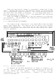
CONNECTIONS AND ADJUSTMENTS FOR RGB REMONSTRATIONS
-
There
are three different modes of operation in the RGB mode:
1.
Red, Green and Blue video with sync on Green
(3
wire).
2.
Red, Green and Blue video with external composite sync
(4
wire).
3.
Red, Green and Blue video with separate horizontal and
vertical sync (5 wire).
1.
Perform the Alignment procedure using the internal test
pattern.
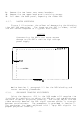
2.
Connect the sync wire/wires to the back panel.
*
Green video for a
3
wire system
*
Composite sync to the sync input for a 4 wire system
*
Horizontal sync to the sync input, vertical sync to
the vertical drive input for a 5 wire system.
3.
Remove the two lower rear cover brackets.
-52-