HARMONY SERIES WHOLE HOUSE WATER SOFTENER OWNER’S MANUAL IMPORTANT! For optimum performance and protection against hard water, please fully read this owner’s manual before proceeding with installation. Version 5.
TABLE OF CONTENTS WELCOME & CONGRATULATIONS 1 EXTENDED WARRANTY REGISTRATION 2 INSPECTION & PREPARATION I. System Review and Installation Tools II. Installation Safety Guide III. Installation Diagram 3 3 4 6 INSTALLING THE SYSTEM STEP 1. Shutting off the main water supply valve STEP 2. Mounting the Control Valve STEP 3. Connecting the Softener STEP 4. Connecting the Brine Tank STEP 5. Flushing and Testing the Plumbing Lines 7 7 8 9 10 12 SYSTEM INITIALIZATION STEP 1.
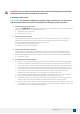
WELCOME & CONGRATULATIONS Thank you for choosing Aquasure. This owner’s manual will guide you through the necessary steps to fully self-install the Harmony water softener. For MAXIMUM effectiveness please thoroughly read this manual. The information listed in this manual covers the steps for a self-serve installation. In the event that you need support, our Aquasure technicians are available to answer any questions during hours of operation as listed below.
DON’T MISS OUT ON FOUR FREE YEARS WITH AQUASURE EXTENDED WARRANTY Register your product within 60 Days from time of purchase to keep your full 5 year warranty. Simply visit aquasureusa.com/support and enter your purchase and serial number, or fill out the information below and follow the steps. Fill in the information below for future reference and submit using the instructions below to receive the extended 4 year product warranty.
INSPECTION & PREPARATION I. System Review and Installation Tools Please take the system and all the components out of the box. Inspect the system and all the connection fittings carefully and make sure nothing was damaged during shipping. If any part is cracked, broken, or missing, please do not proceed with the installation. Contact Aquasure support or your distributor for a diagnosis or exchange. System Components 1. Digital Control Valve 2.
WARNING! For your safety, the information in this manual must be followed to minimize the risk of electric shock, property damage or personal injury. II. Installation Safety Guide IMPORTANT! The following conditions for feed water supply must be met or warranty will be void and the manufacturer assumes no responsibility for damage to system or property. 1.
4. Pre-install environment checklist (Continued) • A 120 volt electric outlet must be within 6 feet of the softener. The transformer has an included 8 foot power cable. Be sure the electric outlet and transformer are protected from water and wet weather. • If installing outside, necessary steps must be taken to ensure the softener, installation plumbing, wiring, etc. are protected from the elements and contamination sources. • Handle with care when moving the water softening system.
III. Installation Diagram The following diagram displays how the water softener should be installed with a well or city water setup. If you have city water, your plumbing arrangement will vary but the installation principles are the same. This is an example of how a pre-filter, media tank and water softener flow in line together. If you do not have a media tank/ carbon filter with your purchase, then exclude it from your installation. A loop installation with shut-off valves is advised as seen below.
INSTALLING THE SYSTEM IMPORTANT! Locate and test the main water supply valve to the home before installing the system. If the main water supply valve fails to shut off the water completely during the test, we recommend contacting your local plumber to fix the valve before installing the system. A B C I F H D G E A. B. C. D. Control Head Bypass Valve Water Connection Hoses (Not Included) Upper Basket E. F. G. H. I.
STEP 2. Mounting the Control Valve 1. Attach the bypass valve onto the control head and secure it with the metal plates. Make sure the o-rings are lubricated before connecting. (Silicone Grease recommended as lubricant.) 2. Make sure the o-rings are lubricated before installing. Lubricate both O-rings on the bottom of the control valve (inner and outer). 3. Lubricate the riser tube located on the opening of the tank. Make sure riser tube is flush with the top of the tank. 4.
STEP 3. Connecting the Softener IMPORTANT! On copper plumbing systems, be sure to install a grounding wire between the inlet and outlet piping to maintain grounding. WARNING! Any solder joints being soldered near the valve must be done before connecting any piping to the valve. Always leave at least 6” (152 mm) between the control valve and joints being soldered when soldering pipes that are connected to the valve. Failure to do this could cause damage to the valve. 1.
STEP 4. Connecting the Brine Tank 1. Connect the brine line to the control valve by removing the blue locking clip on the brine line connector. 2. Push the brine line into the brine line connector and make sure it goes through the o-ring. Secure by pushing in the locking clip. Pull the brine line to see if it is secure. IMPORTANT! Make sure the brine line is secure to the connection provided on the brine tank.
IMPORTANT! This optional brine tank overfill connection step is not required. For additional security against leaks and prevention of disrupted service purposes only. Optional Brine Tank Overfill Connection: Below the brine hose connection you will notice a 90-degree barbed connection facing downward. This connection is optional since the brine well is equipped with an automatic float valve shutoff.
STEP 5. Flushing and Testing the Plumbing Lines WARNING! If the system is leaking at all, turn the unit to the bypass position and shut off main water supply before assessing leak. IMPORTANT! Flushing the system lines is necessary to ensure that all plumbing work has been done correctly, that there is no debris or air trapped in the piping, and that there are no leaks. 1. Place the unit in the bypass position. Locate the nearest faucet and remove aerator (faucet screen) if there is any.
SYSTEM INITIALIZATION STEP 1. Become Familiar with Display Screen IMPORTANT! Each button has multiple functions and has unique features when pressed during different settings or screens. They can be combined with other buttons to execute the different functions of the valve. Please be familiar with the buttons to operate the control valve. 1 2 11:30 1. Flow Meter Indicator 5 (Appears when running water) 3 4 1000 2. Time of Day gAL 3. Status 4. Volume Remaining 5.
STEP 2. System Startup 1. When power is supplied to the control, the screen will display the time of day, gallons remaining and the regeneration mode. Press and hold the “Cycle” button for 5 seconds until you see the words “goto bW ” and then release the “Cycle” button. The backwash (bW ) will be underway. 2. Once the valve is in the backwash (bW ) cycle, you will see the 15-minute (015) countdown next to “bW ”. Open the inlet on the bypass valve slowly and allow water to enter the unit.
Setting 1 - Time of Day (Military Time) IMPORTANT! The system will default to regenerate at 2 am in the morning based on the time entered in the setting. Setting the correct time of the day will ensure that the system regenerates at the corresponding regeneration time. 11:30 Press the ENTER button to adjust the time setting. SEt - 1tIME Flashing Set the hour Flashing Press UP or DOWN buttons to change hours. 11:30 Press the ENTER button to accept and continue.
Setting 2 - Regeneration Type IMPORTANT! The system offers three mode types depending on your needs. It is recommend to set the system at (tM) Time Meter mode which allows the system to regenerate at 2 am in the morning once the gallons reaches zero. 11:30 Press the ENTER button to adjust the regeneration type setting. SEt - 2 tYPE Flashing Choose Between Time, Meter or Meter Delayed Note: It is recommended to set the system to Time Meter.
Setting 3 - Unit Capacity (Not shown if Timer Mode was selected in 2nd Step) IMPORTANT! This setting will only appear if the either (M) Meter or (tM) Time Meter mode from the previous setting was selected. User will not see this setting if (t) Timer mode was selected. The system default is 1000 gallons with the option to change the unit measurement and the capacity of the water treated before the system goes through a regeneration.
4. Regeneration Time and Hours Override IMPORTANT! Depending on the mode selected, the default setting may be set to regenerate at every 72 hours. Even if (M) Meter or (tM) Time Meter mode is selected, the regeneration override will still allow the system to regenerate even if the gallons didn’t count down to zero. It is highly recommended to keep the setting at OFF if (M) Meter or (tM) Time Meter mode was selected. 11:30 Press the ENTER Key to adjust the time and hour override setting.
5. Setting the Back Wash Time (Recommend keeping at factory default setting) (bW) Backwashing time allows the system to flush out any debris or particles that may enter the resin tank. It also helps create space in between the resins to allow more contact surface for the next stage of regeneration. The default setting is 15 minutes. 11:30 Press the ENTER key to adjust the backwash setting. SEt- 5 -bWFlashing Set the Time Default setting is 015 Press UP or DOWN buttons to change Back Wash time (Minutes).
7. Setting the Rapid Rinse Time (Recommend keeping at factory default setting) (rr) Rapid Rinse time allows the system to flush the hardness and residual debris that may be left inside the system out to the drain. The default setting is 10 minutes. 11:30 Press the ENTER Key to adjust the rapid rinse time setting. SEt- 7 -rrFlashing Set the Time Default setting is 010 Press UP or DOWN buttons to change Rapid Rinse time (Minutes).
GALLONS CALCULATION TOOL The control valve head uses a meter to count the gallons of water being treated through the system. Once the gallons programmed in the unit have been exhausted, the system will regenerate. The total gallons of treatable water the system can produce is based on the system size, family size, and the hardness level of the feed water. A simple calculation is done to determine the amount of gallons to input during the “Setting 3” programming portion of the installation.
ONLINE GALLONS CALCULATION TOOL Use your phone to scan the QR code below or visit aquasureusa.com/calculationtool for our online gallons calculation tool. If you need further assistance, contact our support team at support@aquasureusa.com.
ADDITIONAL FEATURES & DISPLAYS 1. Display in Service Timed Regeneration Mode The display will show the current time, remaining time to the next set regeneration, and the days override. 11:30 02:18 01-d Reg. remaining time Meter Regeneration Mode The display will show the current time and the remaining treated water to the next regeneration. Reg. override days 11:30 618 gAL Reg.
4. Manual regeneration Queued Regeneration When the valve is in service position press the button to activate the queued regeneration. Queued Regeneration means the system will initiate a regeneration at the time set. If missed, it will initiate on the next day. The display shows the Queued Regeneration in Meter Delay Mode The display shows the Queued Regeneration in TIMER Mode 11:30 11:30 Flashing Flashing 02:18 ---- 02:18 ---- The display shows the Queued Regeneration in Meter Delay Mode.
TECHNICAL SPECIFICATIONS PRODUCT DIMENSIONS Aquasure Water Softeners Tank Size A 8”x44” 52” 8”x44” 52” 9”x48” 56” 10”x54” 62” 12”x52” 60” 13”x54” 62” Capacity (In Grains) 24,000 32,000 40,000 48,000 64,000 80,000 B 44” 44” 48” 54” 52” 54” C 8” 8” 9” 10” 12” 13” 15" A B 37" C 25 www.AQUASUREUSA.
Flow Rate @ 50 psi (3.5 bar) Valve Alone: Continuous 15 psi (1 bar) Drop: 20 gpm (76 lpm) Peak 25 psi (1.7 bar) Drop: 26 gpm (98 lpm) Max Backwash 25 psi (1.7bar) Drop: 7 gpm (26 lpm) CV 1 psi (0.07 bar) Drop: 5.0 Regeneration/Backwash: Valve Specifications: Inlet/Outlet: 1" or 3/4", NPT Mounting Base: 2-1/2" 8 NPSM Distributor Pilot: 1.
Valve Body Assembly and Parts List Item No. Quantity Part No. Description 1 3 A-12112 Screw 2 1 A-13546 End Plug Retainer 3 1 A-13363 Washer 4 1 A-13296 Screw 5, 6, 7, 8 1 A-60102-20 Piston Softener & Filter 9, 10 1 A-60125 Seals (5) & Spacers (4) Assy. 11 1 A-61400-34 Valve Body Assembly, 3/4" Dist.
1 2 Item No. Quantity Part No.
LIMITED PRODUCT WARRANTY Aquasure warrants to the original retail purchaser that this Harmony Water Softener is free from defects in material and workmanship, and agrees to replace, at Aquasure’s discretion, any defective product free of charge within the warranty time periods from the date of purchase. This warranty extends to the original retail purchaser only and commences on the date of the original retail purchase of the Aquasure Harmony Series water softener system.
NOTES AQUASURE HARMONY SERIES 30
NOTES 31 www.AQUASUREUSA.
AQUASURE HARMONY SERIES 32
www.AquasureUSA.com | 800.661.0680 | support@aquasureusa.