HARMONY SERIES WHOLE HOUSE WATER SOFTENER OWNER’S MANUAL FOR MODEL NO.
TABLE OF CONTENT 2 2 2 3 4 INSPECTION & PREPARATION Understanding How the Water Softener Works I. Be Familiar with the System Before Installation II. System Operation Parameter and Installation checklist III. Installation Safety Guide 5 5 5 6 7 8 10 11 20 INSTALLING THE SYSTEM STEP 1. Shutting off the main water supply valve STEP 2. Installing Bypass Valve onto the Control Head STEP 3. Brine Tank Preparation STEP 4. Softener Preparation STEP 5. Connecting the System STEP 6. System Startup STEP 7.
WELCOME Thank you for choosing Aquasure. Before you starting installing your Aquasure Harmony Series Whole House Water Softener. Please take a few minute to become familiar with the basics. INSPECTION & PREPARATION Understanding How The Water Softener Works The principle behind water softening is simple chemistry. A water softener contains resin beads which hold electrically charged ions. When hard water passes through the softener, calcium and magnesium ions are attracted to the charged resin beads.
II. System Operation Parameter and Installation checklist IMPORTANT! The following condition for feed water supply must be met or warranty will be void and manufacturer assumes no responsibility for damage to system or property. 1. Water Temperature Parameter System must not be installed at an area where it is exposed to direct sunlight and must be protected against freezing and extreme heat. • Maximum: 100º F (37.8º C) • Minimum: 32º F (0º C) 2.
III. Installation Safety Guide • • • • • • Handle with care when moving the water softening system. Do not turn upside down, drop, drag, or set on areas with sharp protrusions. The system works on standard 110v power plug only. Do not use any other transformer except the ones that is included with the system Transformer must be plugged into an indoor 120 volt, grounded outlet only. Use clean water softening salt only with at least 99.5% pure. Extra course grade or crystal salt are recommended.
INSTALLING THE SYSTEM IMPORTANT! Locate and test the main water supply valve to the home before installing the system. If the main water supply valve fails to shut off the water completely during the test, we recommend contacting your local plumber to fix the valve before begin installing the system. WARNING! If the system is installed on a metal (Conductive) plumbing system, i.e.. copper or galvanized metal, the plastic components of the system will interrupt the continuity of the plumbing system.
2. Attached the other end of the bypass valve onto the control head and secure it with the metal plate. Make sure the o-rings are lubricated before installing. STEP 3. Brine Tank Preparation (Skip this step if the brine tank comes preassembled) 1. Attach the four grid plate stand onto each corner of the grid plate. 2. Place the grid plate inside the bottom of brine tank, and brine well cut out on the same side of the brine well holder mount opening. 3.
STEP 4. Softener Preparation 1. Remove the resin tank from carton 2. Lubricate both O-rings on the bottom of the control valve (center and outer). 3. Lubricate the riser tube located on the opening of the tank. 4. Install the upper basket on the bottom of the valve by lining up the tabs, pressing in, then turning the basket counterclockwise to lock it in place. 5. Place the upper basket over the distributor tube and push the valve on the tank. Thread the valve on the tank by turning it clockwise.
STEP 5. Connecting the System IMPORTANT! On copper plumbing systems be sure to install a grounding wire between the inlet and outlet piping to maintain grounding. WARNING! Any solder joints being soldered near the valve must be done before connecting any piping to the valve. Always leave at least 6” (152 mm) between the control valve and joints being soldered when soldering pipes that are connected to the valve. Failure to do this could cause damage to the valve. 1.
8. Push the brine line into the brineline connector and secure it by pushing in the locking clips. Pull the brine line to see if it is secure. 9. Secure the flow regulator by installing the Flow holder with the gasket mounted on the inner brine tank wall and align the opening with the holder. 10. Push the brine line into the white quick connector inside the brine well. 11. Pull on the brine line to see if it is secure. 12.
STEP 6. System Startup 1 11:30 2 5 3 1. Flow Meter Indicator 2. Time of Day 1000 4 GAl 3. Status 4. Volume Remaining 5. Regeneration Mode Timer Meter Immediate Meter Delay Setting Button 1. Enter into setting menu 2. Confirm the current setting, and enter into the next step 3. When used simultaneously with up button, it will enter into master programming Up / Down Buttons 1. Adjust current settings 2. Go one step forward or backward Cycle Button 1. Save the setting and return to service 2.
4. When the backwash cycle is complete, the valve will advance to the brine draw (BD) position. Once the valve reaches the BD cycle, push and release the “Cycle” button. The display will show “GOTO RR” (Rapid Rinse). Once the valve reaches the rinse cycle, allow the water to run for the entire rinse cycle 5. When the rinse cycle is complete, the valve will advance to the “BF” position.
2. Setting the Regeneration Mode 11:30 Default setting is "Timer" SET- 2TYPE NOTE: See page 22 for feature and display in regards to each of the three regeneration mode. Choose the mode that best fit your need. Flashing Choose Between Time, Meter Immediate or Meter Delayed (Recommend Setting the system to Meter Delay) Timer This mode will not show water capacity options. 11:30 TYPE- T Flashing Press Up or Down buttons to change mode Press the Settings Button to accept and continue.
3. Setting the Unit Capacity (Not shown if Timer Mode was selected in 2nd Step) 11:30 Default setting is 1000 gal SET-3 C-U Flashing Set Unit Measurement - Gallons, Liters or Cubic Meters (Recommend setting to Gallons for US Customer) Gallons (Recommended) 11:30 01000 GAL Flashing Press Up or Down buttons to Change Unit between: GAL: Gallon L: Liter M3: Cubic Meter 11:30 Liters 01000 Press the Settings Button to accept and continue.
01000 GAL Flashing 11:30 01000 GAL Flashing Press Up or Down buttons to set water capacity. 11:30 Press the Settings Button to accept, cursor moves left and the number flashes. 01000 GAL Flashing IMPORTANT! Enter the number of gallons that was determined in the Total Gallons Calculation worksheet in page 20. This worksheet must be completed to determine the proper gallons.
4. Regeneration Time and Hours Override (Recommend keeping at factory default setting) 11:30 S E T - 4 T-H Flashing Timer Mode Meter Imm & Meter Delay Modes (Recommended) Default: 2:00 a.m. – 072 hours Hours Override range: 3, 4, 6, 8, 12 hours, then every 24 hours (24, 48, 76… 960) Default: 2:00 a.m.
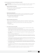
5. Setting the Back Wash Time (Recommend keeping at factory default setting) 11:30 SET-5 -BWFlashing Set the Time Default setting is 015 11:30 015 Press Up or Down buttons to change Back Wash time (Minutes) Range: 0 - 999 Press the Settings Button to accept and continue to next digit -BW- Flashing 11:30 015 -BW- Flashing 11:30 015 -BW- Flashing 16 www.AQUASUREUSA.
6.
7. Setting the Rapid Rinse Time (Recommend keeping at factory default setting) 11:30 SET-7 -RRFlashing Set the Time Default setting is 010 11:30 010 -RR- Flashing Press Up or Down buttons to change the Rapid Rinse time (Minutes) Range: 0 - 999 Press the Settings Button to accept and continue to next digit 11:30 010 -RR- Flashing 11:30 010 -RR- Flashing 18 www.AQUASUREUSA.
8. Setting the Water Filling Time (Recommend keeping at factory default setting) 11:30 SET-8 -BFFlashing Set the Time Default setting is 012 11:30 012 -BF- Flashing Press Up or Down buttons to change the Water Filling Time (Minutes) Range: 0 - 999 11:30 012 Press the Settings Button to accept and continue to next digit -BF- Flashing 11:30 NOTE: Use the table below to determine the proper BF setting for your unit.
TOTAL GALLONS CALCULATION The Aquatrol valve uses a meter to count the gallons of water being treated through the system. Once the gallons programmed in the unit has been exhausted, the system will regenerate. The total gallons of treatable water the system can produce is based on the system size, family size, and the hardness level of the feed water. A simple calculation is done to determine the amount of gallons to input during the programming portion of the installation.
CONGRATULATIONS! You have finished installing your very own water softener. Please document the system installation time and maintain the system at its recommended interval. Don’t forget to register your system to get full 5 years of limited warranty. (System comes with 2 year limited warranty without registration) Simply scan the QR code using your mobile phone, or go directly to our website http://www.aquasureusa.com/warranty-registration to begin the online registration process.
FEATURE & DISPLAYS 1. Display in Service Timed Regeneration Mode The display will show the current time, remaining time to the next set regeneration, and the days override. 11:30 02:18 01-D Reg. remaining time Meter Immediate Regeneration Mode Reg. override days 11:30 The display will show the current time and the remaining treated water to the next regeneration. 60 M3 Reg.
3. Memory during power failure All program settings are stored in permanent memory. Current valve position, cycle step elapsed, time of day are stored during the power failure. Reset the current time is necessity when power up. If the valve stopped at a regeneration stage when power failure, the valve will return to prior position when power up. It takes 4 to 5 minutes to reset to the position. 11:30 The display shows as: The system will show the status when power failure after find the position.
5. Manual regeneration Immediate Regeneration When the valve is in service position, press and hold the button for 5 seconds, an immediate regeneration will be initiated.
PRODUCT DIMENSION VALVE DIMENSIONS Aquasure Water Softeners Tank Size A 8”x44” 54” 10”x54” 64” 13”x54” 64” Model AS-HS32D AS-HS48D AS-HS64D B 46” 56” 54” C 8” 10” 13” 15" A B 37" C AQUASURE HARMONY SERIES 25
SYSTEM TROUBLESHOOT Problem Cause Correction 1) The control fails to Regenerate automatically A) Disconnected meter cable A) Reconnect the meter cable B) Transformer damaged B) Replace the transformer C) Electronic controller or sensor damaged C) Replace or repair 2) Regeneration at wrong time A) Timer improperly set, due to power failure A) Reset timer 3) loss of capacity A) Increase draw water hardness A) reset unit to the new capacity B) Brine concentration or quantity B) Keep brine tank
AQUASURE HARMONY SERIES 27
LIMITED PRODUCT WARRANTY Aquasure warrants that your new water conditioner is built of quality material and workmanship. When properly installed and maintained, it will give years of trouble free service. Five Year Valve, Electronics and Resin Guarantee Aquasure will replace any part on the valve or electronics which fails or the softening resin within (5) five years from date of manufacture, as indicated by the serial number, provided the failure is due to a defect in material or workmanship.
AQUASURE HARMONY SERIES 29
www.AquasureUSA.com | 818 N Mountain Ave #203c, Upland, CA 91786 | 800.661.0680 | sales@aquasureusa.