INSTALLATION AND OPERATION MANUAL SOLAR PUMP CONTROLLER APC-30-250 1|Page IMI-161, Revision D
Table of Contents Introduction…………………………………………………………………………Page 3 Precautions………………………………………………………………….………Page 4 Features…………………………………………………………………………….…Page 5 Installation and Operation……………………………………………………Page 6 Wiring Diagram………………………………………………………………….Page 11 LED Light Quick Reference Guide………………..………………….….Page 12 Trouble Shooting…………………………………………….………………….Page 13 Technical Specifications.………………………………………….……….…Page 14 Notes on your installation…………………………………………………..Page 15 Warranty…………..………………………………….
Introduction The Aquatec APC-30-250 is designed specifically to be an interface between a photovoltaic array, and the Aquatec SWP series submersible pumps. It is a solidstate power converter that optimizes and protects the solar well pump. The controller automatically extends pump run time by the use of current boosting, and provides protection from excessive Voltage and Current, as well as dry-running.
Precautions - Read Documentation thoroughly - Hire a qualified installer if not familiar with safe practices - Disengage power while working.
Features - Weather resistant housing - Can be powered directly from either a solar panel or battery - Low water cut-out via switchless sensing - Over Voltage Protection (manually adjustable) - Over Current Protection - Maximum power point tracking (Regulation of array voltage to match pump load) - Linear Current Boosting to match pump load requirements - Power output adjustability for pump flow control - System power switch - LED status indicators for system power, pump running, low water, open load and ove
Installation & Operation - See pump manual for additional system requirements and recommendations. - Ensure Solar Panel Array is delivering minimum voltage requirements stated on page 8 section 2. - Controller Location: The solar pump controller can be mounted indoors or outdoors. It should be placed in a protected location, mounted vertically close to the well, and oriented to limit direct sunlight exposure. - Wiring: Be sure that wires are not “live” when being connected.
A grounding block terminal is located in the lower left portion of the controller. This can be used to for grounding connections per local codes. - Use proper cable glands to ensure that the controller housing remains sealed - All equipment should be installed prior to making electrical connections to the solar controller. - All materials and work must comply with national and local regulations - Please refer to the following instructions for proper operation: 1.
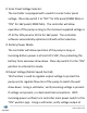
2. Solar Panel Voltage Selector: The controller is equipped with a switch to select solar panel voltage. Place dip switch 1 to “OFF” for 30V panel (180W Min) or “ON” for 36V panel (200W Min). The controller will allow operation of the pump as long as the minimum supplied voltage is 27.5V for 30V panel or 30.5V for 36V panel. The controller software automatically optimizes LCB with either selection. 3.
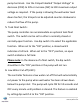
pump terminals. Use the trimpot labelled “Output Voltage” to decrease (CCW) to 20V or increase (CW) to 30V maximum output voltage as required. If the pump is drawing the well water level down too fast, the trimpot can be adjusted counter-clockwise to reduce the flow of the pump. 5. Tank Float Switch: The pump controller can accommodate an optional tank float switch. The switch can be set to either a normally closed or normally open function. Use dip switch 3 to select the applicable function.
The calibration of this feature is performed as follows: a. Place dip switch 4 to the “ON” position. b. With the pump running, raise it above the water line. c. Turn trimpot labelled “LWC” to full counter-clockwise position. d. Slowly turn trimpot clockwise until “Low Water Cut-Off” indicator LED (red) turns on. After a 10 second delay the pump will stop. e. Lower pump below the water line. The pump will start after approximately one minute. f. Raise pump above water line.
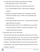
Note: Factory default dip switch settings are as shown above.
LED Light Quick Reference Guide POWER IN ------------------------- GREEN POWER OUT ---------------------- GREEN FLOAT SWITCH ----------------- YELLOW OVER CURRENT ---------------------- RED LOW WATER CUTOFF -------------- RED FEATURE POWER IN POWER OUT FLOAT SWITCH LOW WATER CUTOFF (LWC) OVER CURRENT PROTECTION LED STATUS DESCRIPTION POWER IN LED: OFF No Operation. POWER IN LED: ON (Solid) POWER IN LED: ON (Blinking) Normal Operation. Low Voltage Condition - See page 8 Section 2.
Troubleshooting Guide Fault Possible Cause How to Correct Controller not powering up 1) Wire connection fault 2) Low voltage 1) Inspect wire connections and fuses 2) Check array for proper voltage - See page 8 section 2 Pump will not operate 1) Faulty power supply 2) Wire connection fault 3) Low voltage (Power In LED flashing) 1) Ensure adequate power supply 2) Inspect wire connections and fuses 3) Ensure minimum voltage supplied - 27.5V minimum for 30V (60 cell panel) - 30.
Technical Specifications - Model: ……………………………………………….……….… APC-30-250 - Max Load Power: ……………………………………..….…. 250 Watts - Max Load Current: …………………………………………….... 5 Amps - Max Input Open Circuit Voltage: …………………..….... 48 Volts - Max Regulated Output Voltage: …………………….…… 30 Volts - Enclosure Dimensions: ………………….…. 6.55” x 6.13” x 3.75” - Shipping Weight: ………………………….…………………..….. 2.0 lbs.
- Notes on your installation ---------------------------------------------------------------------------------------------------------------------------------------------------------------------------------------------------------------------------------------------------------------------------------------------------------------------------------------------------------------------------------------------------------------------------------------------------------------------------------------------------
WARRANTY Aquatec Water Systems, Inc. (“Aquatec”) warrants its products to be free from defects in material and workmanship under the following terms: All Aquatec APC solar pump controllers: The warranty will last for a period of eighteen months from date of manufacture.