Series 9000 Water Treatment System Owners Manual Installation Service & Parts Operation Guide The Clear Choice for Soft, Conditioned Water
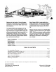
TABLE OF CONTENTS Page Pre-Installation Review -------------------------------------------------------------------------------- 2 Installation Procedures & Start Up----------------------------------------------------------------3-6 System Design & Flow Diagrams --------------------------------------------------------------- 4-12 Valve Parts Diagram & List ----------------------------------------------------------------------- 6-16 Timer-Controlled Model------------------------------------------------------
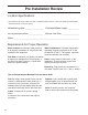
Pre Installation Review Location Specifications: • Not intended to be used to treat water that is microbiologically unsafe or of unknown quality without adequate disinfection before or after the system.
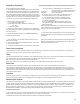
Installation Procedure • System and Installation must comply with state and local codes. Read all instructions before starting! A. Do you want your outside spigots on hard water? If so 1. Unpackage system and visually inspect. Note: If the system place provisions in the water line before entercomes equipped with demand regeneration. The By-Pass valve ing the unit by placing appropriate number of tees and for these units is located in a separate box inside the main box. extending them to the outside.
4
TIMER MODEL installation and start-up procedure 5
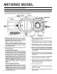
METERED MODEL installation and start-up procedure 6
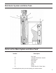
Distributor System and Brine Tank Parts List for Main System and Brine Tank* Item No. 1. 2. 3. 4. 5. 6. 7. 8. Description Not Used Turbulator Distributor System Tank Shroud Brine Well Salt Shelf Resin Media Safety Shut Off - Brine Valve * In ordering these parts you must specify your model number.
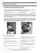
Maintenance Information Quick Disconnect Procedure: 1. Uplug unit from electrical power source. 2. Move the Bypass lever from the “Service” position to the “Bypass” position 3. Turn the Manual Regeneration knob to the “Backwash” position to relieve the pressure. 4. Remove the drain line from the back of the Control Head. 5. Remove the Brine Line from the control valve using a 5/8 wrench. 8 6. Remove the two clips between the bypass and the control valve using a screwdriver or a 1/4” nut driver.
TURBO DISTRIBUTOR water conditioner flow diagrams 9
10
VALVE BODY ASSEMBLY (see parts list) 11
MODEL WCC VALVE BODY ASSEMBLY PARTS LIST 12
BY-PASS ASSEMBLY 13
METERED MODEL meter assembly 14
TIMER MODEL control valve drive assembly (see opposite page for parts list) 15
TIMER MODEL CONTROL VALVE DRIVE ASSEMBLY PARTS LIST 16
TIMER MODEL service instructions 17
18
TIMER MODEL service instructions 19
20
METERED MODEL control valve drive assembly (see opposite page for parts list) 21
METERED MODEL METER INITIATED PARTS LIST 22
METERED MODEL service instructions 23
METERED MODEL service instructions 24
25
METERED MODEL service instructions 26
27
28
LIMITED LIFETIME WARRANTY WARRANTY POLICY AQUA SYSTEMS, Avon IN, warrants this water treatment system as stated herein: From the date of shipment, when we receive any part (or parts) described below, during the specified period below, which we find defective because of faulty materials or workmanship or corrosion we will repair or replace the part (or parts) and return it to you, you pay only freight to and from our factory and local labor and service charges.