
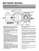
Specifications


Installation Procedure
Read all instructions before starting!
1. Unpackage system and visually inspect. Note: If the system
comes equipped with demand regeneration. The By-Pass valve
for these units is located in a separate box inside the main box.
It is required that the By-Pass valve be installed onto the meter.
To do so simply loosen the 2 adapter clips located on the back of
the meter with a 1/4” nut driver or a screwdriver. Slip the bypass
over the “O” rings on the meter and tighten the adapter clips.
2. Find a location with accessibility to:
A. The main inlet water supply.
B. Adequate drain Fixture, capable of 5 gallons per
min. ow.
C. Electrical Outlets.
3. Place Unit in chosen location, if the oor is not level the unit
may be leveled with the built in adjustable base by lightly tapping
the unit on the oor.
4. There should be a minimum of 12ʼ of Water Line between
softener and water heater.
1. Turn off electric or gas to water heater and the inlet (cold)
water valve to heater.
2. Turn off main water supply to building and drain off pressure
at all cold water outlets.
3. In placing the inlet line to the unit make these considerations.
A. Do you want your outside spigots on hard water? If so
place provisions in the water line before enter-
ing the unit by placing appropriate number of tees and
extending them to the outside.
B. Is there a main shut off valve for the building? If not, a
convenient place for one is in the inlet line to the unit.
C. The inlet water line should be a minimum of 3/4” in
size. If yours is smaller consult our manufacturing plant
for required adjustments.
D. Do not solder ttings directly into the By-Pass valve,
use threaded adapter with a minimum 3” between sweat
tting and By-Pass.
With the above considerations connect the water line to the inlet
of the conditioner which is designated by an arrow pointing toward
the valve of the unit on the By-Pass.
4. Connect the outlet, designated by an arrow pointing away from
the unit on the By-Pass, to the water line that feeds the inside of
the building.
Note: If the building is pre-plumbed with a three way By-Pass that
By-Pass must be inspected. If the By-Pass does not seal 100%
there will be hard water intrusion.
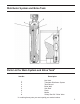
Drain Line Connection
On the back of the water control center there is a 1/2” Threaded port. This is the connector for the system drain. Use only teon
tape on the connection. Do not use pipe dope or paste of any kind.
Note:
You may elevate the drain line up to 6 feet if you are discharging into an open drain and if you have a minimum of 40 psi water pres-
sure at the softener. You may elevate an additional 2 feet for each additional 10 psi over 40 psi.
Also, the total run of the drain line should not exceed 20 feet.
Some codes require, and it is advisable, that you leave a 4” air gap between the drain line and the oor drain.
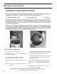
Brine Line
On these units it is necessary to install the brine line between the control valve and the brine tank. A 4 foot piece of
3/8” poly tubing is included with the unit. Install one end of the tubing to the compression elbow at the brine tank making sure the
brass sleeve is inserted into the tube before hookup. Install the other end of the tubing into the compression nut on the right hand
side of the control valve making sure to rst insert a brass sleeve into the tubing and then insert the brine screen (included) into the
brass sleeve. Tighten ttings.
Overow
Each unit has the provision for connecting an overow drain line. On the brine tank is a slip tting for 5/8” plastic line. This should be
run to an area where a small amount of spillage would be accepted in the event a malfunction should occur.
• System and Installation must comply with state and local codes.
To Disinfect the System:
1. Add 1.2 uid ounce of 5.25% sodium hypochlorite solution (household bleach; Clorox, Bo Peep, etc.) for each cubic foot of resin to
the brine well of the brine tank. ( the 4” tube with a cap on it inside of the brine tank)
2. Manually start a normal regeneration. Allow the system to complete the regeneration.
The materials of construction of the modern water conditioner will not promote bacterial growth, nor will these materials contaminate
a water supply. However, the normal conditions that exist during shipment, storage and installation make it advisable to disinfect a
conditioner after installation, before the conditioner is used to treat potable water. In addition, during normal use, a conditioner may
become fouled with organic matter, or in some cases, with bacteria from the water supply. Therefore every conditioner should be
disinfected after installation, some will require periodic disinfection during their normal life.
Sanitizing the System
3