
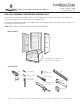
Instructions / Assembly


— 2 —
Aquatic • 8101 E. Kaiser Blvd. • Anaheim, CA 92808 • (800) 877-2005 • FAX (714) 998-5340 • www.aquaticbath.com
Installation Data
Freedomline 4-Piece Showers
F1364P, F1424P*, F1604P
Fax on Demand # 1163
Aquatic products may be specified as Lasco Bathware.
NOTICE: Please inspect the unit thoroughly before installation to make sure it has not been damaged during transportation. Under no
circumstances should a damaged unit be installed. Neither Aquatic nor the distributor will be responsible for removal or reinstallation costs
should a replacement be necessary due to installation of a damaged unit.
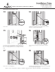
PRE-INSTALLATION PLANNING
1. Review job print and Aquatic rough-in dimensions; verify all key dimensions against actual job conditions.
2. Make sure framed-in alcove is of proper size, square and plumb; check floor for level.
3. If fire-rated alcove is required, approved finish material must be in place prior to unit installation to meet fire safety
requirements of local building code and/or FHA/HUD Minimum Property Standards. NOTE: Finished alcove must have
interior dimensions shown on rough-in diagram to permit installation of unit.
4. Foundation materials [industrial plaster, mortar mix, lightweight grout] are mandatory under the bottom of each unit to solidify
for wheelchair support.
5. Provide 6” (150mm) floor opening for 2” (50mm) IPS and drain connection.
6. Make sure all plumbing is complete and to code.
7. To avoid obstruction, make sure that supply lines and valve plumbing do not project into alcove during the installation
process. Also, drain pipe must not project above floor level prior to installation.
8. On inside of plumbing wet wall of unit, note location of supply elbow and mixer valve.
9. To prevent scuffing while installing unit, cover the floor of the unit with a piece of cardboard or other protective material.
10. Fasteners for:
Wood framing - 1 1/2” galvanized roofing nails or #10 x 1 1/2” self-tapping washer head screws.
Concrete or block walls - 1” concrete nails and nailing tool.
Steel studs (18 ga.) - drill flanges and studs with 5/32” carbide bit and use #12 x 1” sheet metal screws.
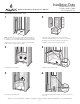
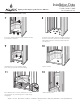
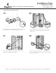
INSTALLATION INSTRUCTIONS
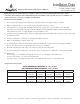
MODEL # DIM. A DIM. B DIM.C DIM. D SKIRT HEIGHT
F1364P 39 7/8”
(1015 mm)
19 15/16”
(505 mm)
39”
(990 mm)
19 7/8”
(505 mm)
1 1/4”
(30 mm)
F1424P 45 7/8”
(1165 mm)
22 15/16”
(585 mm)
51 1/8”
(1300 mm)
7 7/8”
(200 mm)
1 1/4”
(30 mm)
F1604P 63 7/8”
(1620 mm)
31 15/16”
(810 mm)
37 1/8”
(945 mm)
18 7/8”
(480 mm)
1 1/4”
(30 mm)
WIDTH DIMENSIONAL TOLERANCE +0, –3⁄8” (±5 mm)
ALL OTHER DIMENSIONAL TOLERANCES ± 3/8” (±5 mm)