FastSCAN TM TM Cobra and Scorpion TM Handheld Laser Scanner User Manual printed March 2014 Revision 4.
Copyright c 1998–2014 by Aranz Scanning Ltd 110 Papanui Road Merivale, Christchurch, 8014 New Zealand PO Box 3894 Christchurch, 8140 New Zealand www.aranz.com www.fastscan3d.com All rights reserved. No part of this publication may be reproduced, stored in a retrieval system, or transmitted in any form or by any means—mechanical, photocopying, recording or otherwise—without the prior written permission of ASL. No patent liability is assumed with respect to the use of the information contained herein.
FastSCAN Before You Begin... Please read and fully understand Section 12: Safety Guidelines before using the FastSCANTM Scanning equipment. This section contains important safety information.
ii FastSCAN Contents 1 Introduction 2 Hardware and Software Setup 2.1 Components . . . . . . . . . 2.2 Computer Requirements . . 2.3 Installing the Software . . . 2.4 Connecting It All Together . 2.4.1 Installing the Drivers 2.5 Running FastSCANTM . . . . 3 4 5 1 . . . . . . . . . . . . . . . . . . . . . . . . . . . . . . . . . . . . . . . . . . . . . . . . . . . . . . . . . . . . . . . . . . . . . . . . . . . . . . . . . . . . 2 2 4 4 5 5 6 Scanning 3.1 The Scanning Environment . .
FastSCAN 5.1 5.2 5.3 5.4 5.5 iii Basic Surface . . . . . . . . . . Basic Surface Parameters . . . 5.2.1 Smoothing . . . . . . . 5.2.2 Decimation: . . . . . . 5.2.3 Limit Objects to: . . . 5.2.4 Surface Simplification: 5.2.5 Apply Basic Surface: . Registering the Sweeps . . . . Surface Information . . . . . . Batch Processing . . . . . . . . 6 Generating an RBF Surface 7 Exporting a Surface 7.1 Export Options . . . . . . . 7.1.1 File Types for Export 7.1.2 Export Formats . . . 7.2 Delta . . . . . . .
iv FastSCAN 14 Customer Service 57 15 Limited Warranty and Limitation of Liability 58 16 Indemnity Against Patent Infringement 60
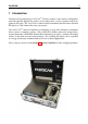
FastSCAN 1 Introduction Thank you for purchasing a FastSCANTM 3D laser scanner. Your scanner will quickly and conveniently digitize the surface of any object into a series of points that fit together in 3D space. The FastSCANTM software then transforms this data into a detailed 3D object, in a file format that suits your needs. The FastSCANTM software combines overlapping sweeps and eliminates redundant data to create a complete surface.
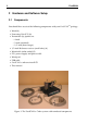
2 FastSCAN 2 Hardware and Software Setup 2.1 Components You should have received the following components with your FastSCANTM package: • Wand (1) • Processing Unit (PU) (2) • Transmitter (3), options are: • • • • • • • ◦ 4 inch ◦ 2 inch (standard) ◦ 1/2 inch (short ranger) 1/2-inch Reference receiver (small cube) (4) Wand cable (color coded) (5) PU’s power supply and power cable Wand pad USB cable FastSCANTM software install CD This manual.
FastSCAN Optional Items • Mechanical Stylus • Optical Stylus 3
4 FastSCAN 2.2 Computer Requirements • Windows Vista or XP (SP2) 32 or 64 bit OS, or Windows 2000 SP4. ◦ 1 GHz Intel Pentium III or greater (2 GHz Intel Pentium IV or greater recommended for RBF processing) ◦ 512 MB RAM or greater. ◦ USB port. • OpenGL compatible hardware accelerated graphics adapter in 32-bit (true color) mode (minimum resolution 1024 x 768). 2.3 Installing the Software Important: In order to install FastSCANTM ensure you have administrator privileges on the computer.
FastSCAN 2.4 5 Connecting It All Together Note: Ensure that the PU is switched off before any of the front panel leads are connected or disconnected, or the Wand is detached from its cable. 1. Place the PU near the computer and plug it into a power source using the power pack and cable. Connect the USB cable to the front of the PU and to the computer. Allow room for air circulation at the back of the PU. 2.
6 FastSCAN 5. It is normal for Windows to report that FastSCANTM drivers have not passed Windows Logo testing/are not digitally signed by Microsoft. Click Continue Anyway each time when prompted until the drivers are installed. Note: This procedure needs to be repeated when plugging the scanner into a different USB port. For Windows Vista: 1. Before powering up the PU connected to your computer click: Start/Settings/Control Panel to open the Control Panel window. 2. Double-click on System. 3.
FastSCAN 7 Figure 3: The FastSCAN startup screen. Figure 4: The Scanner Properties dialog box.
8 FastSCAN 4. The status indicator at the bottom right of the screen (labeled 1 in Figure 3) should change from Scanner disabled to Scanner initializing... After approximately 10 seconds this should change to Scanner on-line, indicating that the system has initialized. Note: Do not depress the trigger while the Wand is initializing. 5. When setting up the system for the first time or changing Wands open the Scanner Properties box (Figure 4) via Scanner/Properties... . 6.
FastSCAN 3 3.1 Scanning The Scanning Environment An area of subdued lighting is ideal for scanning, with no external light entering from windows. Scanning errors can arise when the scanner’s camera views direct sources of strong, bright light, such as the sun or a powerful incandescent light. Keep the scanning area at least one meter away from the Processing Unit, computer, and any other significant metal objects. A wooden table is an ideal surface on which to place objects for scanning.
10 FastSCAN Note - Multiple standard FastSCANTM systems will not work alongside one another without interference. This can be remedied with a replacement Frequency Module. Contact your vendor if required. 3.2 The Wand The FastSCANTM Wand is available in 2 models—the CobraTM and the ScorpionTM . The CobraTM is a light and compact single-camera Wand suited to most applications. The double-camera ScorpionTM can enable faster scanning and be more effective where occlusion is potentially a problem.
FastSCAN 11 Handling the Wand • The Wand is a sensitive optical instrument—handle it with care at all times. • Place the Wand carefully on the Wand pad when not in use. • After finishing your scanning session switch off and return the Wand to its protective case. • If the Wand is mishandled or dropped it will need calibrating. 3.2.
12 FastSCAN Scanning position (trigger pulled in completely): • displays laser profiles and surface data on the screen in real-time and stores them in memory • illuminates both the Laser and Scan LEDs. Note: If the scanning equipment is set up incorrectly the Laser and Scan lights may flash alternately when the trigger is depressed into either position. 3.2.2 Wand Sensitivity The Sensitivity Control allows you to compensate for different subject surface types, colors and lighting conditions.
FastSCAN 3.3 13 Scanning With the Wand The Transmitter is Reference option is the default setting for a typical scanning situation (a small–medium size stationary object; the Tx icon selected) and normally this button should always be selected. To scan unstable or large objects you may need to use the Receiver as Reference (Rx icon)—see Section 3.5. 3.3.1 Scanning Technique To scan a complete object you will need to perform a number of sweeps with the Wand.
14 FastSCAN For best scan results: • allow the wand to warm up for 5 minutes before scanning an object • minimize the distance of the Wand from the object to increase the accuracy of the scan.
FastSCAN 3.3.2 15 Scanning Resolution - Limits Control In some situations you may wish to place a limit on the resolution at which data is collected, e.g. to reduce memory and processing requirements. This can be achieved by adjusting the Best Scanning Resolution in the Scanner Limits Control dialog box (accessed from Scanner/Limits Control). You can control the coarsest scanning resolution at which data is collected via the Worst Scanning Resolution in the Scanner Limits Control dialog box.
16 FastSCAN You can control the amount of smoothing using the Profile Smoothing option in the Scanner Limits Control dialog box (High, Medium, Low (default), or Off—see Figure 10) (Note: Smoothing cannot be turned off when using the ScorpionTM ). Changing this value affects newly captured profiles—it cannot change data that you have already collected. You may need to experiment to find the optimal value before you begin scanning. Figure 11 shows how smoothing can affect a profile.
FastSCAN 3.5 17 Using the Secondary Receiver - Rx as Reference By attaching a secondary receiver (Rx) to the subject it becomes possible to move and/or reposition the subject while building up the scan, allowing full 360◦ coverage. This can also be used to compensate for small movements that may occur in the subject while scanning or to scan large objects. 3.5.1 Moving the Subject During Scanning Attach the Receiver firmly to the object you are scanning.
18 3.5.3 FastSCAN Scanning Large Objects You can also use the Reference Receiver to scan extra large objects. Fix the Receiver to the center of the object and place the Transmitter midway between the Receiver and the Wand. As you move around the object also move the Transmitter, keeping it within 100 mm and 750 mm of the Receiver and Wand (Figure 13). Figure 13: Scanning a large T-shaped object with Receiver as Reference.
FastSCAN 3.6 3.6.1 19 Viewing Options Data View/On Screen Format The appearance of the data can be changed by clicking on View and choosing from the 3 options: Points, Wireframe and Solid, or their icons in the toolbar. These allow you to view the data in different formats and use this information to get the best possible scan. Many of these functions can be performed via the keyboard Hotkeys. See Section 9.1 for a full list.
20 FastSCAN Bounding Box: The Bounding Box enclosing the perimeter of the data is used in the RBF surfacing process and, in coordination with the Extents Window, gives the physical size of the object. It can also be useful for users needing a file for CAD systems or wanting a watertight model or closed object. Click on View/Bounding Box to see the Bounding Box.
FastSCAN 3.6.2 21 Other Viewing Variables Viewpoint: The data/object can be moved on-screen by clicking and dragging with the mouse or by clicking on View/Viewpoint and selecting the desired direction. Shortcut keys to use these functions via the keyboard are also listed here. Movement: Clicking on View/Movement allows you to set the speed at which the data/object changes position when manipulating it using the View/Viewpoint options or the keyboard. Normal Fine Very Fine Ultra Fine Rotate 30.0◦ 5.
22 FastSCAN Tracking: View/Tracker Positions enables you to see where the Transmitter, Wand and Reference were during the scan, which can assist in improving the quality of your scanning. Lighting and Colors: Settings/Lighting and Colors allows you to change the object, laser and background colors as well as altering the position and strength of the lighting on the object, enabling easier viewing of hard to see areas, or those previously in shade.
FastSCAN 4 4.1 23 Processing Scanned Data Surfacing Options The FastSCANTM software deals with three surfaces: the Sweeps Surface, the Basic Surface and the RBF Surface. Figure 16 shows the path taken to generate these three surfaces. Figure 16: Objects and processes in the FastSCANTM program. The display view may be changed between the Sweeps Surface, Basic Surface and RBF Surface. If processing is required to obtain a view it will begin automatically when that display option is selected. 4.1.
24 FastSCAN 4.1.2 Basic Surface The Basic Surface is generated from the Sweeps by: • merging overlapping sweeps • changing and filtering the data • standardizing the resolution • simplifying the triangular mesh (optional) • limiting the number of objects (pieces of data contained in the Sweeps (optional)). 4.1.
FastSCAN 4.3 25 Scan Files 4.3.1 Opening and Saving Scans New Scan: To commence a New Scan click on File/New or the New icon in the toolbar. Open: To Open a scan click on File/Open or the Open icon in the toolbar. Only .fsn and .hls file formats can be opened. Saved scans can be processed and exported, but you cannot add more sweeps to them after exporting. Save As: To Save a scan under a new name or format click on File/Save As or the Save As icon in the toolbar. Scans can only be saved in the .
26 4.4 FastSCAN Editing Raw Data 4.4.1 The Sweeps During scanning your data appears on-screen as the Sweeps. You can revert to this view at anytime during the surfacing process by clicking on View/Sweeps or on the Sweeps icon in the toolbar. 4.4.2 The Sweeps List You can view a log of all the sweeps in a scan by clicking on Edit/Sweeps List.... This log allows you to view each sweep individually and to remove single sweeps from your scan if desired.
FastSCAN (a) With some sweeps highlighted, and Selected Sweep Transparent box unchecked. 27 (b) With some sweeps highlighted, and Selected Sweep Transparent box checked. Figure 18: Scan with highlighted sweeps, showing color differences. With (a) only visible parts of selected sweeps shown (b) all parts of selected sweeps shown, with different color shades.
28 FastSCAN Use the Flip Sweep button to turn the selected sweep(s) inside out. This reverses the orientation of the sweeps, and can be used to make a mould with further processing. 4.4.3 Selecting and Deleting Data It is possible to delete unwanted or inaccurate areas of the scan. Change the cursor to a selection tool by either choosing Edit/Select, clicking on the Select icon in the toolbar or by holding down the Ctrl key. Then left-click-and-drag the mouse to enclose the area you wish to delete.
FastSCAN 5 29 Generating A Basic Surface 5.1 Basic Surface Creating a Basic Surface removes redundant points in overlapping sweeps. The scanned points can be repositioned and the minimum distance between them fixed to determine the amount of detail present in the final surface. When you have sufficiently edited your Raw Data click on the Basic Surface icon to generate the Basic Surface.
30 FastSCAN Figure 19: The Generate Surface dialog If the FastSCANTM program does not merge the overlapping sweeps correctly when it creates the Basic Surface, the surface will appear ‘blistered’. Figure 21 shows how the blistering occurs as the Basic Surface jumps between the points in the two sweeps. 5.2.2 Decimation: Increasing the Decimation value in the Generate Surface dialog box (Figure 19) reduces the number of points and triangles.
FastSCAN 31 (a) Smoothing at 0.5 mm. (b) Smoothing at 2 mm. Figure 20: Two Basic Surfaces generated from the same Sweeps using different Smoothing parameters. In (a) the sweeps did not combine correctly, while in (b) they did. Figure 21: An illustrative example of how a blistered surface (black line) can form between two misaligned sweeps (gray lines). ter. Smaller Decimation values will have more blistering, while larger values may be completely free of it.
32 FastSCAN (a) 6 mm Decimation (b) 9 mm Decimation Figure 22: The same object at different decimation values. The 6 mm version (a) has 1378 triangles, while the 9 mm version (b) has only 704 triangles. (Scorpion models only, refer Section 10.3). • Perform a User Calibration to ensure the optics are correctly aligned (see Section 10). 5.2.
FastSCAN 5.2.5 33 Apply Basic Surface: When you have set the Basic Surface Processing values click on the Apply Basic Surface button to generate the Basic Surface. 5.3 Registering the Sweeps The various sweeps of the scan may not always overlap perfectly. This may be due to: • small errors in the scanner measurements • metal objects interfering with the magnetic locater • the object or reference moving unintentionally during scanning.
34 FastSCAN (a) The object with artifacts visible on the Basic Surface. (b) The object after Register Sweeps has been used. Figure 23: Register Sweeps is used to better align the Sweeps and remove any artifacts. 5.5 Batch Processing The Batch Processing interface allows you to process and export several scan files at once, each with different parameters if required. Figure 24 shows the batch processing dialog. Select File/Export As/Batch Process to open the Batch Processing dialog.
FastSCAN 35 Figure 24: The Batch Processing dialog. Generate Surface Settings... button opens the Generate Surface dialog, where you can specify the surface parameters for the Basic Surface or RBF Surface. The Output control displays and allows you to change the output file’s format and filename. The default output filename is the scan filename. Click the Add button to add a new scan to the list.
36 6 FastSCAN Generating an RBF Surface See the FastRBFTM Extensions Manual for instructions on how to generate an RBF surface. While an RBF surface may be generated with the unlicensed FastSCANTM software, a license is required to enable saving of the surface.
FastSCAN 7 37 Exporting a Surface 7.1 Export Options You can export a surface at any stage of processing—the file formats available are determined by what stage you are at. FastSCANTM can export files in a number of industry standard formats. We have attempted to support the most popular variant(s) for each—if you have difficulties importing one of these files into your 3D application, try exporting another variant or format. If you continue to have difficulties, please go to our website (www.aranz.
38 FastSCAN 7.1.2 Export Formats FastSCAN TM lets you export your data in the following formats: Polyworks Line Scan (.psl) A binary file format for saving the sweeps only. It consists of raw scan data requiring further processing. 3D Studio (.3ds) The file format used by 3D Studio and supported by 3D Studio Max; also supported by other programs. This format supports cloud of points or triangle mesh data. Ascii (.txt) ASCII stores a plain-text list of vertex locations.
FastSCAN 39 Matlab (.mat) A binary data file format used by The MathWorks MATLAB. Supports cloud of points or triangle mesh data, both with optional vertex normal vectors or pseudo gray-scale values. The file will contain five MATLAB variables at most: • Points: A 3-by-N matrix where each column is a vertex location. • Normals: A 3-by-N matrix giving the vertex normal vector for each vertex. • Facets: A 3-by-M matrix where each column defines a triangle as three indexes into the list of Points.
40 7.2 FastSCAN Delta Click on the DeltaTM icon to load the scan data directly into DeltaTM software—you must have DeltaTM installed. DeltaTM is a stand alone tool that enables comparison of surface distance and volume variations between two objects. You will need a license to use the DeltaTM software. A demonstration copy of DeltaTM can be downloaded from: http://www.fastscan3d.com /download/. 7.3 Save Snapshot Selecting File/Save Snapshot creates a .
FastSCAN 41 Figure 26: Example of a Saved Snapshot file Figure 27: The Save Snapshot dialog box (with advanced options).
42 FastSCAN 9 9.
FastSCAN 43 Hotkey List cont’d... Menu Item Shortcut View/Movement/Normal View/Movement/Fine View/Movement/Very Fine View/Movement/Ultra Fine Ctrl+1 (object moves by 30.0◦ ) Ctrl+2 (object moves by 5.0◦ ) Ctrl+3 (object moves by 1.0◦ ) Ctrl+4 (object moves by 0.2◦ ) decrease movement size by 1 decrease movement size by 2 decrease movement size by 3 Exit from current edit mode Shift+mvmt key (↑←↓→) Ctrl+mvmt key (↑←↓→) Shift+Ctrl+mvmt key (↑←↓→) Esc 9.2 9.2.
44 FastSCAN For more information on Cast Inversion Mode refer to the Cast Inversion Manual or contact Aranz Scanning Ltd (scanning@aranz.com, www.aranz.com, www.fastscan3d.com). (A license is required to enable this function.) 9.2.3 Laser Pointer/Mark with Mouse/Stylus Mode The Laser Pointer, Mark with Mouse and Stylus modes enable the user to place reference points and/or lines on the surface of the scanned object.
FastSCAN 10 45 Calibration The Wand is fully calibrated before it leaves the factory. However, for optimum performance you may need to check the calibration from time to time. This process is quick and convenient. You should check the Wand calibration if: • the Wand has been knocked or dropped • you notice the visual quality of the scans has deteriorated • you have not used the FastSCANTM Wand for some time • you are about to commence a particularly difficult or demanding scan.
46 FastSCAN Figure 29: The Transmitter with the Calibration Target attached. Note: While in Calibration Correction mode, the FastSCAN program monitors the Wand-to-Target distance and will only accept data when the distance is within ±20 mm of the nominal value. 100 mm data: range is 80 mm to 120 mm. 200 mm data: range is 180 mm to 220 mm. You may find maintaining the correct distance while scanning the Calibration Target is awkward at first.
FastSCAN 47 4. Start the FastSCANTM program (if you are running Windows 2000 or XP then you must have at least Power User privileges). 5. Click on Scanner/Calibration Correction.... The background color of the FastSCANTM window will change to black and the Calibration Correction dialog box will appear (Figure 30). 6. Set the sensitivity control of the Wand to position 1. 7. Hold the Wand at a range of 100 mm (4”) above the Calibration Target. 8.
48 FastSCAN Figure 30: Three of the four calibration spot clusters are visible (for the ScorpionTM ) and the Calibration Correction dialog box. Notes: • You must collect the 100 mm data first. • Windows 2000 or XP users must have Power User privileges or greater. • If desired the most recent sweep (or the point in this case) can be removed with a double click of the trigger, or all data can be removed with a triple click. These functions are switched on by default—see Section 3.4.
FastSCAN 10.3 49 Alignment Check (Scorpion Users Only) The Alignment Check is a simple test to assess the alignment of the optics and is independent of the tracking system. Perform an Alignment Check as follows: 1. From the FastSCANTM software, select Scanner/Alignment Check. 2. Position a sheet of white paper (US-letter or A4) near the Transmitter. 3. Set the sensitivity control to position 1. 4.
50 11 FastSCAN Troubleshooting/FAQs Q. The status bar of the FastSCANTM program continues to show ‘Scanner off-line’— what has gone wrong? A. Run through the following checklist: • Ensure you do not have another FastSCANTM program still running from an earlier session (possibly minimized). • Ensure that power is getting to the PU. The green ‘Power’ light on the front panel should be on. • Ensure that power is getting to the Wand. The green ‘Power’ light on the Wand should be on.
FastSCAN 51 object’s surface during scanning, but no closer than 80 mm to keep within the camera’s field of view. If you are using the Receiver, parts of the surface closer to it will scan more accurately. Try to keep the Transmitter close to the Wand and Receiver, as accuracy deteriorates with distance, but no closer than 100 mm to avoid signal overload. The maximum separation of any two components is about 750 mm, but for best results, keep them as close as possible. Q.
52 FastSCAN 12 12.1 Safety Guidelines FCC Statement This equipment has been tested and found to comply with the limits for a Class A digital device, pursuant to part 15 of the FCC Rules. These limits are designed to provide reasonable protection against interference when the equipment is operated in a commercial environment.
FastSCAN 53 • Operate the device so that it is pointing away from windows, doors, mirrors and other shiny reflective surfaces, and areas where other people are working. • There are no controls, adjustments or user serviceable parts that can affect the laser output. In the event of equipment failure, return the Wand to the manufacturer or agent for repair and servicing. The product includes the following safety features: • The laser is only activated when the spring-loaded trigger is depressed.
54 FastSCAN 12.4 Warning Labels and Locations (a) The Wand displaying warning labels. (b) Warning labels. (c) Close-up of the laser aperture (circled), and twoposition trigger switch (bottom).
FastSCAN 13 55 Distributors Master Distributor: POLHEMUS PO Box 560, 40 Hercules Drive, Colchester, VT 05446 United States of America Ph. 802/655-3519 Fax. 802/6551439 http://www.polhemus.com Austria: EST, Engineering Systems Technologies GmbH &Co. KG www.est-kl.com Croatia: VR Logic www.vrlogic.com Denmark/Finland: Contact sales@polhemus.com Australia: Aranz Scanning, StormFX Pty Ltd www.aranz.com www.fastscan3d.com www.stormfx.com.au Belgium: Immersion SA, IMAQs www.immersion.fr www.imaqs.
56 FastSCAN Italy: Unocad S.R.L, GEA Media Group S.R.L www.unocad.it www.geamedia.com Singapore: Interactive Dreams Pte Ltd www.id-dreams.com/020115/044/ welcome frame.htm Japan: KBK-Kyokuto Boeki Kaisha Ltd www.kbk.co.jp/cesd/polhemus.htm Spain: Aplein Ingenieros S.A www.apleiningenieros.com/ South Korea: Jek Co Ltd idkwon@jek.co.kr Sweden: Contact sales@polhemus.com Luxemborg: IMAQS www.imaqs.com Switzerland: EST Engineering Systems Technologies GmbH & Co. KG www.est-kl.
FastSCAN 14 57 Customer Service If you encounter any problems with your FastSCANTM system, help is just a telephone call away. Call 802/655-3159 (800/357-4777 U.S. and Canada) and ask for Customer Service. For the most part, our Customer Service engineers can handle your problems over the telephone and get you back into the fast lane right away. If the problem requires repair of your instrument, the Customer Service engineer will issue you a Return Merchandise Authorization (RMA) number.
58 15 FastSCAN Limited Warranty and Limitation of Liability 15.1 Polhemus warrants that the Systems shall be free from defects in material and workmanship for a period of one year from the date ownership of the System passed from Polhemus to Buyer. Polhemus shall, upon notification within the warranty period, correct such defects by repair or replacement with a like serviceable item at Polhemus’ option.
FastSCAN 59 15.5 Warranties shall not apply to any Systems which have been: (a) repaired or altered other than by Polhemus, except when so authorized in writing by Polhemus. (b) used in an unauthorized or improper manner, or without following normal operating procedures; or (c) improperly maintained and where such activities in Polhemus’ sole judgement, have adversely affected the Systems.
60 16 FastSCAN Indemnity Against Patent Infringement Polhemus shall have the right at its own expense, to defend or at its option to settle, any claim, suit or proceeding brought against Buyer on the issue of infringement of any United States patent by any product, or any part thereof, supplied by Polhemus to Buyer under this Agreement.