
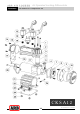
Install Drawing

ARB AIR LOCKER
Air Operated Locking Differentials
Revision Date 14/09/05
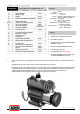
CKSA12
On-Board Air Compressor Kit
Specs:
ITEM # QTY DESCRIPTION PART # NOTES
01 3 HEAD BOLT 310202
Voltage
12 Volts
02 1 HEAD ASSEMBLY 310102
Current Draw
No-Load 5A
03 1 BARREL O-RING --- 1
Load 6.5A
04 1 BARREL 310201
Air Flow
25.0L/min @ 0kPa [0.88CFM @ 0psi]
05 1 BARREL GASKET --- 1
13.4L/min @ 200kPa [0.47CFM @
06 1 PISTON/COUNTERWEIGHT ASSEMBLY 310103
Total Wei
g
ht
2.1kg [4.6lbs]
07 1 CRANKCASE COVER GASKET --- 1
Size
122mm x 162mm x 188mm
08 1 CRANKCASE COVER --- 2
[4.8” x 6.4” x 3.5”]
09 & 16 1 COVER BOLTS (M4 HEX FLANGE) 310203
Manifold Port
1
/
4
” npt [Pressure Switch]
10 1 AIR FILTER ASSEMBLY 300501 7
1
/
8
” bspt [Solenoid nipple]
11 1 AIR FILTER ELEMENT 300502 5 Pressure Switch
Open 690kPa [100psi]
12 2 SOLENOID ASSEMBLY
NOT SUPPLIED
Closed 490kPa [70psi]
13 1 PRESSURE SWITCH CO35
14 2 PLUG (1/8” BSPT) 170802 4
15 1 MANIFOLD O-RING --- 1
17 1 MOTOR/CRANKCASE ASSEMBLY --- 2
18 2 MOTOR BOLT O-RING --- 1
Notes:
19 1 MANIFOLD COVER --- 2
20 2 MOTOR BOLT --- 2
1 Available only in CKS SEAL KIT #310104.
21 1 MOTOR MOUNT ASSEMBLY 310101
22 4 MOUNTING BOLT 200405
2 Not available separately.
23 2 MOTOR MOUNT CLAMPING NUT --- 3
24 1 COMPRESSOR BACKING PLATE 290603
3
Available only as included with MOTOR MOUNT
25 4 MOUNTING NUT 6151223
ASSEMBLY #310101.
26 2 MOTOR MOUNT CLAMPING BOLT --- 3
* 1 SWITCH COVER (COMPRESSOR) 180212
4 Included x2 in HEAD ASSEMBLY #310102.
* 1 SWITCH 180209
* 1 WIRING LOOM,CKSA12 180408 6
5 Available only in packs of 3.
* 1 INSTALLATION GUIDE 2102SA12
* 1 SCOTCH LOCK ELEC. CONNECTOR CO45
6 For wiring diagram refer to
Section 5.8.
7 AIR FILTER ASSEMBLY comes complete with
*
Not illustrated in exploded view.
one AIR FILTER ELEMENT (Item #11)
NOTE:
The air filter should be cleaned regularly. To do this, unclip the filter cover (10) and remove the element (11). Wash in hot,
soapy water, rinse and let dry completely. Reinsert the element into the base. Wipe out the cover and clip firmly back into
place.
All screws in this unit have been thread locked using a special high heat compound. Dis-assembly of this unit should only be
attempted using a heat gun or micro torch to pre-heat each thread prior to loosening it.
The compressor manifold must be periodically removed to clean out any condensation, etc. To do this, bleed off any residual
pressure that may be in the manifold. Remove the 4 cover bolts at the end of the manifold and the 3 head bolts (01). Remove
the manifold and wipe out any moisture. If there is excessive moisture in the manifold then it should be cleaned out more
regularly. Refit the manifold making sure that the O-rings are in their correct position. Torque the bolts up to
1.28Nm [0.94ft-lb]. Do not over tighten. Run the compressor and check for any air leaks.
3.3