Gladius G0975 9.7” Intel® Celeron® N2930 Rugged Tablet PC User's Manual Version 1.0 P/N: 4019097500100P 2014.
This page is intentionally left blank.
Revision History Version Date Descriptions 1.0 2014.
Copyright Copyright © 2014 ARBOR Technology Corp. All Rights Reserved. This document contains proprietary information protected by copyright. No part of this manual may be reproduced by any mechanical, electronic, or other means in any form without prior written permission of the manufacturer. Disclaimer The information in this document is subject to change without prior notice in order to improve the reliability, design and function. It does not represent a commitment on the part of the manufacturer.
Contents Contents Preface...........................................................................................................v Declaration of Conformity.......................................................................................v CE....................................................................................................................v FCC Class B....................................................................................................v RoHS.........................
Contents 3.1.2.1 On-screen Keyboard............................................................22 3.1.2.2 Handwriting Recognition......................................................23 3.2 Function Keys.................................................................................................24 3.2.1 Using the Function Keys.......................................................................24 3.2.2 Customizing the Function Keys............................................................24 3.
Preface Preface Declaration of Conformity CE The CE symbol on your product indicates that it is in compliance with the directives of the Union European (EU). A Certificate of Compliance is available by contacting Technical Support. This product has passed the CE test for environmental specifications when shielded cables are used for external wiring. We recommend the use of shielded cables. This kind of cable is available from ARBOR. Please contact your local supplier for ordering information.
Preface • • Connect the equipment into an outlet on a circuit different from that to which the receiver is connected. • • Consult the dealer or an experienced radio/TV technician for help. RoHS ARBOR Technology Corp. certifies that all components in its products are in compliance and conform to the European Union’s Restriction of Use of Hazardous Substances in Electrical and Electronic Equipment (RoHS) Directive 2002/95/EC. The above mentioned directive was published on 2/13/2003.
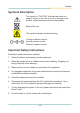
Preface Symbols Description This symbol of “CAUTION” indicates that there is a danger of injury to the user or a risk of damage to the product, should warning notices be disregarded. Battery Recycle This symbol indicates electrical warning. Change of electric current: Internal: positive current External: negative current Important Safety Instructions Read these safety instructions carefully: 1. Read all cautions and warnings on the equipment. 2. Place this equipment on a reliable surface when installing.
Preface 9. Never use any of the solvents, such as Thinner Spray-type cleaner, Wax, Benzene, Abrasive cleaner, Acid or Alkaline solvent, on the display. Harsh chemicals may cause damage to the cabinet and the touch sensor. 10. Remove dirt with a lightly moistened cloth and a mild solvent detergent. Then wipe the cabinet with a soft dry cloth. 11. The openings on the enclosure are for air convection and protect the equipment from overheating. DO NOT COVER THE OPENINGS. 12.
Preface -20° C (-4° F) OR ABOVE 60° C (140° F). THIS MAY DAMAGE THE EQUIPMENT. Rechargeable Battery Pack Safety • • Important Terms to Understand “Battery life” means the time the equipment will run before it must be recharged (sometimes this is also called “playtime” or “runtime”). “Battery lifespan” means the total amount of time your battery will last before it must be replaced. • • Using the Equipment for the First Time Be sure to fully charge (approx.
Preface • • Don’t disassemble the battery, or the battery leakage might cause skin or eye injury. If electrolyte leaking from the battery contacts your skin or clothing, immediately flush it with running water. If it splashes into eye, rinse the eye at least 15 minutes with clean water and then seek medical attention. • • To avoid battery leakage or explosion, don’t discard the battery into water or fire, or put them near a heat source such as a gas stove or an oven.
Preface Cleaning Tools Although many companies have created products to help improve the process of cleaning your devices and peripherals, users can also use household items to clean their devices and peripherals. Below is a listing of items you may need or want to use while cleaning your devices or peripherals. Keep in mind that some components in your device may only be able to be cleaned using a product designed for cleaning that component, if this is the case it will be mentioned in the cleaning.
Preface Disposing of the Computer • • Within the European Union EU-wide legislation, as implemented in each Member State, requires that waste electrical and electronic products carrying the mark (left) must be disposed of separately from normal household waste. This includes monitors and electrical accessories, such as signal cables or power cords.
Preface Additional Information & Technical Support All ARBOR products are built to the most accurate specifications to ensure reliable performance in the harsh and demanding conditions typical of industrial environments. Whether your new equipment is destined for the laboratory or the factory floor, you can be assured that the computer will provide the reliability and ease of operation. Your satisfaction is our primary concern. We want you to get the maximum performance from the computer.
Preface Warranty This product is warranted to be in good working order during the warranty period. Should this product fail to be in good working order at any time during this period, we will, at our option, replace or repair it at no additional charge except as set forth in the following terms. This warranty does not apply to products damaged by misuse, modifications, accident or disaster.
1 Chapter 1 Introduction Chapter 1.
Introduction 1.1 Product Highlights The G0975 Series is a rugged mobile tablet PC featuring a compact 9.7” XGA IPS LED display and 5MP rear camera. Designed for mobile field applications, the G0975 Series weighs just 1.0 kg and integrates Wi-Fi and Bluetooth wireless connectivity for seamless wireless communication. Compliant with IP65 and MIL-STD-810G shock & vibration standard, the G0975 Series also comes with sealed I/O ports and sturdy rubber bumpers on each of its four corners for enhanced protection.
Introduction 1.2 Package Contents Upon opening the package, carefully inspect the contents. If any of the items is missing or appears damaged, contact your local dealer or distributor. The package should contain the following items: 1 x G0975 Computer 1 x Driver CD 1 x User’s Manual 19V/3.42A 65W AC/DC Adapter Kit 2270mAh External Battery Pack 1.2.1 Order Information G0975 9.
Introduction 1.3 Specifications System CPU Intel® Celeron® Processor N2930 quad-core 1.83 GHz Graphics Controller Intel® HD Graphics Memory 2GB DDR3L SO-DIMM memory module installed (optional up to 8GB) BIOS UEFI BIOS 1 x integrated microphone Audio 2 x piezoelectric speaker 1 x 3.5 mm headset combo jack Storage 1 x 32GB MLC mSATA SSD Peripherals and Devices WLAN Integrated WLAN 802.11 a/b/g/n Bluetooth Integrated Bluetooth 4.0 BLE, class 2 Camera 5.
Introduction Touch Screen Type 10-point Projected Capacitive Touch w/ Corning® Gorilla® Glass Light Transparency 80% (typ.) Controller Interface USB Interface LCD Display Size/Type 9.7” XGA IPS LED Display Max. Resolution 1024x768 (XGA), w/ 262,144 Colors Luminance 350 cd/m² (typ.) Contrast Ratio 500 : 1 View Angle (U/D/R/L) 89°/89°/89°/89° Backlight Type LED Power Supply Adapter Input 100 ~ 240VAC (Full Range) Adapter Output 19VDC, 3.
Introduction Transit Drop 1.2m (4ft.) per MIL-STD-810G for whole unit IP Rating IP65 Regulatory CE EN55022 class B FCC 47 CFR, Part 2 and Part 15 OS Support Windows Embedded 7 / Windows 7 Professional Windows 8.1 Embedded Standard / Windows 8.1 Embedded Industry / Windows 8.1 Embedded Professional Ordering Information G0975 9.7” Intel® Celeron® N2930 rugged tablet PC with XGA LCD, projected capacitive touch, battery pack, WLAN, Bluetooth and rear camera G0975S 9.
Introduction 1.4 Dimensions 260.21 258 30.6 A 24 197.95 200.26 22.
This page is intentionally left blank.
2 Chapter 2 Getting Started Chapter 2.
Getting Started 2.1 Getting to Know the Computer 2.1.1 Front Side Power status LED Microphone Battery status LED Wi-Fi LED Bluetooth LED Home Key Function keys Touch screen • • Microphone The built-in microphone captures sound and voice when used with a program capable of recording audio. • • Touch Screen The computer comes with a 10-point projected capacitive touch screen allowing users to interact with the computer without a mouse or keyboard. See 3.
Getting Started • • Status LED Icon LED Power Color Green Status Descriptions On The computer is in main power mode. Blinking The computer is in sleep mode. Off No power is present. The battery is not charged. On Current battery level: 50% ~ 100%. Green Blinking *Current battery level: 16% ~ 49%. Orange Blinking Blinking Green Bluetooth Blue Current battery level: 16% ~ 49%. *Current battery level: 0% ~ 15%. Red Wi-Fi Battery charge is in process. The battery is not charged.
Getting Started • • F1: To enable/disable the Wi-Fi function. • • F2: To enable/disable the Bluetooth function. • • F3: To launch/close the camera utility. • • F4: To launch/close ARBOR System Suite. For more information, see 3.2 Function Keys on page 24. • • Home Key Press to go back to Windows home screen. 2.1.2 Left and Right Sides RST mini-HDMI port Audio out jack Power button Micro USB 2.0 Type-A port microSD card slot USB 2.0/3.
Getting Started Items Descriptions Audio out 3.5mm combo audio/microphone jack. To connect to a set of headphones or speakers. Micro USB 2.0 Type-A port To connect to a USB device. To insert a microSDXC/SDHC/SD card. microSD card slot When inserting the card, make sure to position the card as the graphic indicates, and fully insert the card into the slot until it cannot be inserted any more. To connect to a USB device. USB 3.0/2.
Getting Started 2.1.3 Bottom Side Docking Connector • • Docking Connector 8-pin connector for connection with desktop or vehicle-mount cradle. 2.1.4 Rear Side Auto Focus Camera Speaker Speaker Battery Chamber • • Auto Focus Camera A 5.0 MP CMOS auto-focus camera with LED flash. For more information, see 3.5. Using the Camera on page 32. • • Speaker Piezoelectric speakers for audio output. • • Battery Chamber External battery pack chamber. To replace or install the battery pack, see 2.
Getting Started 2.2 Installing Memory Card The computer has a microSD card slot. You can insert a microSD card to provide additional storage space or use it for file transfer. To install a microSD card to your computer: 1. On the left side of the computer, open the upper rubber cover and locate the microSD card slot. 2. Position the card as the graphic indicates. 3. Fully insert the card into the slot until it clicks into place. 4. Close the microSD card slot cover. 2.
5. The inside of the battery chamber comes to view. Power connector 6. Find the power connector for the external battery inside the battery chamber as illustrated above. To remove an existing external battery, disconnect the battery’s power cable first and then remove the battery. To install a new external battery, plug the battery’s power cable to the power connector first. 7. Fit the battery into the chamber and restore the chamber cover. 8. Secure the cover with the screws you removed in Step 4.
2.4 Charging the Battery Pack To recharge the battery inside the computer: 1. Connect the power adapter to the computer’s power jack and a power source. You can find power adapter & cord in the accessory box. 2. The battery LED indicator ( ) blinks to indicate that charging is in progress. The battery LED color changes according the battery level as described in the Status LED section in 2.1.1 Front Side on page 10. When the battery is fully charged, the battery LED indicator lights solid green.
In addition, the CD includes a number of optional utilities. You may install those utilities as needed. See the table below for the CD-DOM content and the driver needed to be installed for the computer: Driver Type Necessity Descriptions Chipset Required TXE Required Install the Intel Trusted Execution Engine and Trusted Connect Service to enable Intel Trusted Execution Engine Interface. Graphic 64/32bit Required Install the graphics driver. Select 64 or 32-bit according to your operating system.
2. Insert the provided CD to the CD-ROM drive. In a few seconds, a dialog box opens asking what to do with the disc. Tap Run AUTORUN.EXE to auto-run the driver CD. 3. Tap Win7 Driver Install or Win8 Driver Install according to your operating system. If you want to browse the CD contents, tap Browse CD instead. 4. The drivers menu then opens. Tap Chipset to install the chipset driver first.
Make sure to install the chipset driver first. 5. Follow the on-screen instructions to proceed. 6. After installing the chipset drivers, proceed to install the remaining drivers, including TXE, Graphic, DPTF, MBI, Wi-Fi, Bluetooth and Audio. When installing the remaining drivers, there is no need to follow any specific order. The installation process of each driver is basically the same. Just follow the on-screen instructions to proceed.
3 Chapter 3 Using the Computer Chapter 3.
Using the Computer 3.1 Using Touch Screen The computer comes with a projected capacitive touch screen. Touch control is the main way and an intuitive way to interact with the computer. Users are able to manipulate icons, graphic buttons, menus, property sheets, the on-screen keyboard or any on-screen items with touch control. This chapter will walk you through the basic operations for touch control. 3.1.
Using the Computer The thumb keyboard The touch keyboard The handwriting panel Exit the on-screen keyboard 3. To use the touch or thumb keyboard, just enter text by tapping the keys. 3.1.2.2 Handwriting Recognition “Handwriting Recognition” is an input method that interprets and converts handwriting to text. The Windows features a “writing pad” to get the job done. To launch the Windows handwriting panel: 1. Tap the keyboard icon on the Windows taskbar to open the Input Panel as described in 3.1.2.
Using the Computer 2. Write in the writing area. Then tap the bottom-right Enter button to enter the text in a text field. 3.2 Function Keys 3.2.1 Using the Function Keys The computer comes with four function keys enabling you to quickly execute certain programs or functions. If you didn’t install the ARBOR System Suite, a function key association program available in the provided CD (see 2.5 Driver Installation on page 17), then the functions of these keys are defined by Windows system.
Using the Computer ARBOR System Suite shortcut in the notification area 2. The ARBOR System Suite then opens on-screen. For the key that you want to reassign a function, simply tap the intended function. Assigned function will be highlighted in blue. Function key assignment panel Status bar For more information on using the ARBOR System Suite, see 4.1 ARBOR System Suite on page 36.
Using the Computer 3.3 Using the Wi-Fi Feature The computer is built-in with a Wi-Fi module for Wi-Fi networking. Once the driver is installed as described in 2.5 Driver Installation on page 17, a Wi-Fi signal strength icon shows up in the notification area. Wi-Fi icon in the notification area The following descriptions assume that you have installed the ARBOR System Suite to use the function key. Follow the guide below to connect the computer to a Wi-Fi hotspot: 1.
Using the Computer Note: If you didn’t install the ARBOR System Suite and want to launch the Wi-Fi function, please refer to Windows online help on how to turn on Wi-Fi. 2. Tap the Wi-Fi signal strength icon in the notification area. 3. A list opens and shows the Wi-Fi hotspots available within the wireless coverage of the computer. 4. Tap the desired network to connect it. If the network to connect is a secured network, a dialog will open and request for the password.
Using the Computer 3.4 Using the Bluetooth Feature Bluetooth enables the wireless connection over a short distance about 8 meters. It is specified as a “wireless personal area network” (WPAN). The computer is Bluetooth-enabled to synchronize data with other Bluetoothcapable devices such as PCs, laptops, hands-free, headsets, printers, PDAs and cell phones. Once the Bluetooth driver is installed as described in 2.5 Driver Installation on page 17, you can start to use the Bluetooth function.
Using the Computer Note: To conserve power, always power off the Bluetooth module when it isn’t used. 3.4.2 Pairing/Connecting with Other Bluetooth Devices Before the computer can connect with other Bluetooth devices, it has to pair with them. To pair/connect with other Bluetooth devices: 1. Launch the Bluetooth module as described in 3.4.1 Launching the Bluetooth Feature on page 28. 2. From the notification area, tap the Bluetooth icon . 3. A context menu opens.
Using the Computer 3.4.3 Bluetooth Device Name By default, the computer’s Bluetooth device name is the computer name that is viewable at Control Panel | System and Security | System. 3.4.4 Hiding/Exposing the Computer By default, the computer is NOT discoverable by other Bluetooth devices. To hide or expose the computer: 1. Launch the Bluetooth module as described in 3.4.1 Launching the Bluetooth Feature on page 28. 2. From the notification area, tap the Bluetooth icon - 30 - .
Using the Computer 3. A context menu opens. Select Open Settings from the context menu. 4. The Bluetooth Settings dialog box then opens. Tap the Options tab and find the Discovery section. To make your computer discoverable to Bluetooth enabled devices, select the check box of Allow Bluetooth devices to find this computer or otherwise deselect the check box to make it undiscoverable.
Using the Computer 3.5. Using the Camera The computer comes with a ready-to-use camera without the need to install additional drivers. You can use the camera to take pictures or videos. 3.5.1 Launching the Camera To launch the camera: 1. Assign a function key to launch the camera module. 2. Launch the camera module by hitting the function key. The system shows the camera status in the bottom right corner of the screen. Hitting the function key will toggle on/off the camera function.
Using the Computer 3.5.2 Taking a Picture To take a picture: 1. Launch the camera as described in 3.5.1 Launching the Camera on page 32. The camera program automatically launches. 2. From the camera application program’s tool bar, tap the take-a-picture icon . The camera then proceeds to take a picture and save it to local disk (by default at C:\) | Users | (your username) | My Documents | ccd.) 3.5.3 Shooting a Video To shoot a video: 1. Launch the camera (also the camcorder) as described in 3.5.
Using the Computer The camera program automatically launches. 2. From the camera program’s tool bar, tap the configuration icon . The Properties dialog box opens. 3. Make the configuration as needed. 4. Tap the Apply button to apply the changes. Tap the OK button to save the changes and exit the dialog box. Or tap the Cancel button to quit the changes and exit the dialog box.
4 Chapter 4 Utilities Chapter 4.
Utilities 4.1 ARBOR System Suite The Arbor System Suite is a utility to control the computer’s physical function keys F1 through F4. With this ARBOR System Suite, users can associate a function key to turn on/off one of the computer’s features or to launch a specific application program installed on the computer. 4.1.2 Accessing ARBOR System Suite With the Arbor System Suite installed on your computer, tap the Arbor System Suite shortcut System Suite.
Utilities 4.1.3 Using ARBOR System Suite To re-assign a function to a function key, simply tap the intended icon for the desired key. The icon turns to be blue to indicate it’s assigned. See the table below for the meaning of each icon. Note: The panel shows all possible functions across various computer models. Not all functions are available in your computer. Icons Descriptions Associates a function key to turn on/off 3G. Associates a function key to turn on/off Wi-Fi.
Utilities Icons Descriptions Associates a function key to open/close Arbor System Suite. Associates a function key to open/close on-screen keyboard. Associates a function key to open/close a program installed in the system. When tapping the icon, you will be prompted to select a program to associate with. Browse the Windows to select the executable file of the program to associate.
5 Chapter 5 BIOS Chapter 5.
BIOS A BIOS (Basic Input/Output System) is a special utility usually stored in the ROM on the motherboard inside a computer. When you turn on the computer, the BIOS is immediately activated. During the startup, it checks and loads necessary information to ensure the computer can proceed with loading the operating system. The BIOS Setup Utility is typically accessed with a special key sequence, such as “Delete” or “Esc” key as soon as the computer is powering up.
BIOS Keys Descriptions Enter Select or enter a submenu Esc On the Main Menu – Exit the setup and not save changes into CMOS. + / F6 Increase a numeric value. - / F5 Decrease a numeric value. F9 Load the optimal defaults. All settings will be set to the optimal defaults at startup. F10 Save the changes that have been made and exit the BIOS Setup Utility. On the Sub Menu – Exit current page and return to main menu. 5.
BIOS The Main setup screen provides the following information and options: Info / Item Descriptions BIOS Version Displays the computer’s BIOS version. Project Name Displays the computer’s model name. EC Version Displays the current version of Embedded Controller. Processor Type Displays the computer’s processor type. System Bus Speed Displays the processor speed. System Memory Speed Displays the system memory speed. Cache RAM Displays the cache RAM size. Total Memory Displays the total RAM.
BIOS Main Advanced Security Rev. 5.0 InsydeH20 Setup Utility Power Boot Exit Configures Boot Settings. Boot Configuration PCI Express Configuration Miscellaneous Configuration Thermal Configuration SATA Configuration F1 Help Select Item F5/F6 Change Values F9 Setup Defaults ESC Exit Select Menu Enter Select SubMenu F10 Save and Exit 5.3.
BIOS Settings Descriptions XX PCI Express Root Port: Enables/disables this PCIe port. XX PCIE Port Speed: Select the PCIe port speed. Options are: Auto [default], Gen 1, Gen 2 XX PCI Express Root Port 1/2/3/4 PCIE Port ASPM: Select an ASPM (Active-State Power Management) mode to manage the PCI Express serial link devices in order to reduce power consumption.
BIOS Settings Dynamic Platform& Thermal Framework Descriptions DPTF Feature: Enables/disables the DPTF (Dynamic Platform&Thermal Framework) feature. Note: You must install the DPTF driver as described in 2.5 Driver Installation on page 17 to use this feature. The following items are available only when DPTF feature is enabled. Thermal Sensor: Enables/disables thermal sensor.
BIOS 5.4 Security Settings The Security setup screen allows you to configure BIOS security settings to keep unauthorized people from making any changes to the BIOS. Main Advanced Security Rev. 5.0 InsydeH20 Setup Utility Power Boot Exit Supervisor Password Install or Change the password Not Installed and the length of password must be greater than one character.
BIOS 5.5 Power Settings The Power setup screen contains only one item “Advanced CPU Control” which allows you to configure the CPU power mode. Main Advanced Security Rev. 5.0 InsydeH20 Setup Utility Power Boot Exit These items control various Advanced CPU Control CPU parameters.
BIOS 5.6 Boot Settings The Boot menu configures how to boot up the system such as the configuration of boot device priority. Main Advanced Security Rev. 5.0 InsydeH20 Setup Utility Power Boot Exit Quick Boot Quiet Boot Timeout Allows InsydeH20 to skip certain [0] tests while booting. This will decrease the time needed to boot the system.
BIOS Settings Descriptions Boot Device Priority Normal Boot Menu: Select a boot option priority. Options: Normal [default], Advance When Normal is selected, the following items are available: Legacy Boot type order: Change boot type order. Hard Disk Drive: Change hard disk drive. When Advance is selected, the hard disk drive info will be displayed. 5.7 Exit Options The Exit screen provides the options regarding saving changes, quitting the utility and recovering defaults. Main Advanced Security Rev.
BIOS The Exit screen provides the following options: Settings Descriptions Exit Saving Changes Save the changes and exit the BIOS Setup Utility. Exit Discard Changes Exit the BIOS Setup Utility without saving the change(s). Restores all settings to defaults. Load Optimal Defaults After selecting this item, a dialog box will pop up to confirm your choice.