Gladius G0710(S) Rugged Tablet PC User's Manual Version 1.0 P/N: 4012071000100P 2009.
This page is intentionally left blank.
Index Contents Copyright Notice................................................................i Declaration of Conformity.................................................i Important Safety Instructions..........................................ii Classification....................................................................iii Disposing of Your Old Product.......................................iv Symbols Description.......................................................iv About User's Manual...........
Index 2.5.4 Audio Driver Installation...............................27 2.5.5 LAN Driver Installation..................................29 2.5.6 Wireless LAN Driver Installation..................31 2.5.7 Bluetooth Driver Installation........................32 2.5.8 RFID Driver Installation.................................36 2.5.9 Function Key Tray Installation.....................39 2.6 Touch Screen............................................................41 2.6.1 Tips for Using the Stylus.................
Copyright Notice All Rights Reserved. The information in this document is subject to change without prior notice in order to improve the reliability, design and function. It does not represent a commitment on the part of the manufacturer. Under no circumstances will the manufacturer be liable for any direct, indirect, special, incidental, or consequential damages arising from the use or inability to use the product or documentation, even if advised of the possibility of such damages.
IEC 60601-1/EN60601-1 This product complies with the system standard IEC 60601-1 Medical Electrical Equipment Part 1: General Requirements for Safety. And therefore, the product is exclusively interconnected with IEC 60601-1 certified equipment in the patient environment. Equipment connected to the analog or digital interfaces of the unit must comply with the respective IEC standards (e.g. IEC 60601-1 for medical equipment).
10. Never pour any liquid into openings. This may cause fire or electrical shock. 11. Never open the equipment. For safety reasons, the equipment should be opened only by qualified service personnel. 12. If one of the following situations arises, get the equipment checked by service personnel: a. The power cord or plug is damaged. b. Liquid has penetrated into the equipment. c. The equipment has been exposed to moisture. d.
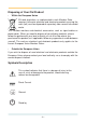
Disposing of Your Old Product • Within the European Union EU-wide legislation, as implemented in each Member State, requires that waste electrical and electronic products carrying the mark (left) must be disposed of separately from normal household waste. This includes monitors and electrical accessories, such as signal cables or power cords.
About User's Manual This User's Manual is intended for experienced users and integrators with hardware knowledge of personal computers. If you are not sure about any description in this User’s Manual, please consult your vendor before further handling. Warning Any changes or modifications not expressly approved by the guarantee of this device could void the user’s authority to operate the equipment.
Warranty This product is warranted to be in good working order for a period of one year from the date of purchase. Should this product fail to be in good working order at any time during this period, we will, at our option, replace or repair it at no additional charge except as set forth in the following terms. This warranty does not apply to products damaged by misuse, modifications, accident or disaster. Please be advised that disassembling this equipment may void the warranty as well.
General Information 1 Chapter 1 General Information Chapter 1 - General Information - -
General Information 1.1 Packing List Tablet PC 1 x Gladius G0710(S) Rugged Tablet PC Accessories 1 x AC to DC Power Adapter 1 x Power Cord 1 x User’s Manual 1 x Driver CD 1 x Stylus 1 x Stylus-Pen Rope Before up and running, please make sure the package contains all of above accessories. If any of the above items is damaged or missing, contact your vendor immediately. 1.2 Ordering Information G0710-CF 7" Intel Atom™ tablet PC with 4GB CF G0710-HDD 7" Intel Atom™ tablet PC with 60GB 1.
General Information 1.3 Specifications Model Name Gladius G0710(S) Rugged Tablet PC CPU Intel Atom Z510 1.1GHz with 400MHz FSB Chipset Intel® System Controller Hub US15W Graphics Controller GMA 500 Integrated Memory Soldered onboard 1GB DDR2-533 SDRAM Audio Azalia HD Audio codec ALC888-GR 1 x 4GB CompactFlash (default) Storage 1 x 60GB 1.8" slim IDE HDD (option) System Realtek 8111B PCI-E Gigabit Ethernet 802.11 b/g/n WLAN Connectivity Bluetooth 2.0 + EDR module RFID Camera I/O HSUPA (3.
General Information LCD Display Touch Panel Display 7” wide active matrix TFT Resolution 1024 x 600 resistive touch panel Brightness 375 cd/m2 (typ.) Contrast 400:1 Backlight Type LED Panel Type Resistive Transparency 73% (typ.) Power Input: 100 ~ 240VAC Power System Power Adapter Battery Power Output: 20VDC, 90W (G0710) 20VDC, 60W (G0710S) Li-ion battery pack 4S1P 2600mAH; Approximately 4hrs charged battery life 210 x 36 x 160 mm (8.26" x 1.42" x 6.
General Information 1.
General Information 1.5 Introduction As an ultra slim and ultra light unit which is easily to access, the tablet PC is equipped with a 7” active matrix TFT panel with a touch screen in front of it. The enclosure of the unit is IP54 compliant; and designed with the Intel Atom Z510 processor that consumes ultra low power, the system using passive ventilation does not rely on fans which are often unreliable. Besides, the system features instant resume and long charged battery life up to four hours.
General Information 1.5.1 Front Side Battery LED HDD LED Bluetooth LED RFID LED Power LED Microphone CMOS Camera Speaker Function Buttons Note: The eight function buttons (F1 ~ F8) on the front panel are available after users have installed the Function Key utility. These buttons can be defined by users. The Control Buttons table below lists the default value for each function button.
General Information 1.5.2 Function Buttons Button Description Brightness Up Press to increase brightness Brightness Down Press to decrease brightness Volume Up Press to increase speaker volume Volume Down Press to decrease speaker volume Mute Press to enable/disable sound Bluetooth Press to enable/disable Bluetooth connectivity Wi-Fi Press to enable/disable Wi-Fi connectivity Touch Press to lock/unlock the touch screen. 1.5.
General Information 1.5.4 Rear Side CMOS Camera Stylus Battery Note: There are two CCD camera located on the front and rear panels respectively. Only one CCD camera functions at a time.
General Information 1.5.5 Right Side Reset button Rubber cover attachment USB port RJ-45 LAN port DC power jack Power button 1.5.
Using the Tablet PC 2 Chapter 2 Using the Tablet PC Chapter 2 - Using the Tablet PC - 11 -
Using the Tablet PC 2.1 Getting Started This chapter is intended to give users the information about how to utilize the various function of the tablet PC. To be familiar with using the computer, please take a few minutes to read this manual. Before installing operating system and driver utilities, you should prepare your own USB keyboard and USB CD ROM drive, and the power adapter included in the package if the battery charge level is insufficient.
Using the Tablet PC 2.2 Battery Replacement The tablet PC is equipped with a 4S1P rechargeable battery pack. When you want to replace the battery or remove it for SIM card installation, please follow the steps below: 1. Disconnect the DC power plug and turn off the computer. 2. Remove any peripheral devices connected to the computer. 3. Unscrew the screw which fixes the battery to the unit. 4. Remove the battery. 5. Insert the new battery into the battery compartment and fix it with the screw.
Using the Tablet PC Instructions for Rechargeable Battery Pack How to recharge: • To recharge the Lithium-ion battery pack, install it into the computer and then connect the power adapter to the power input plug of the computer. • The battery will be fully charged within 2-4 hours (depending on the capacity of the battery). When finished charging, the charge indicator will turn on steadily in green and then it’s recommended to remove the adapter from the computer.
Using the Tablet PC or fire, or near a heat source such as a gas stove or an oven. • Use the appropriate container to store the battery such as a paper box. Do not allow a metal object to touch the terminals of the battery. • When storing for a long period of time, keep the battery approximately at the charging state of 60 ~ 80% and regularly use it.
Using the Tablet PC 2.3 SIM Card Installation When you want to insert the SIM card (only for HSUPA-0710), please follow the steps below: 1. Disconnect the DC power plug and turn off the computer. 2. Remove any peripheral devices connected to the computer. 3. Unscrew the screw which fixes the battery to the unit. 4. Remove the battery. 5. Insert the SIM card into the SIM card slot with the gold-colored contacts facing down. 6.
Using the Tablet PC 2.4 DC Power Supply Apart from the battery pack, the table PC can also be powered by the AC to DC power adpater. If the battery is running low, you can immediately plug the DC connector into the power jack of the computer. With the DC power being supplied, the battery pack attached to the unit charges.
Using the Tablet PC 2.5 Drivers & Utilities Installation 2.5.1 Touch Screen Driver Installation 1. Click Touch Panel to install the driver for touch screen. 2. When you see the welcome wizard, click Next to continue.
Using the Tablet PC 3. Please read the license agreement first, and click I Agree to continue. 4. Click Browse to change the installation directory, or immediately click Install to continue.
Using the Tablet PC 5. Please wait for a while until the progress bar completes. 6. The installation is completed. Click Finish to close this window.
Using the Tablet PC 2.5.2 Chipset Driver Installation 1. Click Chipset of the main menu to install the chipset device driver. 2. Make sure you have closed all programs running and then click Next to continue.
Using the Tablet PC 3. Please read the license agreement first, and click Yes to continue. 4. Please read the License Aggrement by pulling down the scroll bar, and click Next to continue.
Using the Tablet PC 5. The chipset device driver installation is completed. Click Finish to close the window.
Using the Tablet PC 2.5.3 Graphics Driver Installation 1. Click VGA of the main menu to install the graphics device driver. 2. Make sure you have closed all programs running and then click Next to continue.
Using the Tablet PC 3. Please read the license agreement first, and click Yes to continue. 4. Please read the Readme file for system requiremsnts and installation information, and click Next to continue.
Using the Tablet PC 5. The graphics device driver installation is completed. Click Next to continue. 6. After installing the graphics device driver, click Finish with Yes radio button selected to restart your computer to have the changes take effect, or with No to restart this computer later.
Using the Tablet PC 2.5.4 Audio Driver Installation 1. Click Audio of the main menu to install the audio device driver. 2. Click Next to continue.
Using the Tablet PC 3. After installing the audio device driver, click Finish with Yes radio button selected to restart your computer to have the changes take effect, or with No to restart this computer later.
Using the Tablet PC 2.5.5 LAN Driver Installation 1. Click LAN of the main menu to install the LAN device driver. 2. Click Next to continue.
Using the Tablet PC 3. Click Install to start installation, or Back to go back to the previous step. 4. Click Finish to close the wizard window.
Using the Tablet PC 2.5.6 Wireless LAN Driver Installation 1. Click Wireless LAN of the main menu to install the wireless LAN device driver. 2. The installation is in progress; when the progress bar reaches the end, the installation is completed.
Using the Tablet PC 2.5.7 Bluetooth Driver Installation 1. Click Bluetooth of the main menu to install the Bluetooth device driver. 2. A dialog box shows up. Click the down arrow to drop down the selection menu and choose a language item and then click OK to continue.
Using the Tablet PC 3. Check the driver information and click Next to continue. 4. Please read the license agreement first; select I accept the terms in the license agreement and then click Next to continue.
Using the Tablet PC 5. If you want to create shortcuts to Startup folder or Desktop, tick the check boxes beside the text label and then click Next to continue. 6. Click Next to install to this folder, or click Change to install to a different folder.
Using the Tablet PC 7. Click Install to start installation, or click Back to go back to the previous step. 8. After the installation is completed, click Finish to close the window.
Using the Tablet PC 2.5.8 RFID Driver Installation 1. Click RFID of the main menu to install the RFID and USB devices driver. 2. Read the driver information and then click Next to continue.
Using the Tablet PC 3. Click Next to install to this folder, or click Browse to install to a different folder. 4. The driver is being installed, please wait for a while.
Using the Tablet PC 5. Click Finish to complete the installation. Note: After installation, the RFID device information in Device Manager may appear with an exclamation mark. To solve this problem, please manually update the driver for this device, just once.
Using the Tablet PC 2.5.9 Function Key Tray Installation 1. After you put the CD-ROM into the CD-ROM drive, the driver and utility installation main menu appears. Click FunctionKey to install the function key configuration utility. 2. Click Next to continue.
Using the Tablet PC 3. When the installation is completed, click Finish to close the window.
Using the Tablet PC 2.6 Touch Screen 2.6.1 Tips for Using the Stylus With the touch screen driver installed, users can use the stylus like a computer mouse to control the computer. Tapping with the stylus is equivalent to clicking with the left button of a mouse. For the right button behavior, tap anywhere on the screen and hold down until the menu is shown. Also, users can have the mouse icon showing on the right side of the screen (see the next section—PenMount Monitor).
Using the Tablet PC 2.6.2 PenMount Monitor The PenMount Monitor icon (PM) appears in the system tray at the bottomright corner when you turn on PenMount Monitor in PenMount Utilities. Tap on the PM icon and hold down for the pop-up menu shown below. PenMount Monitor has the following functions: Control Panel Launch the PenMount Control Panel utility. Beep Set the Beep function for each device. Right Button After ticking this item, a mouse icon right side of the screen.
Using the Tablet PC 2.6.3 PenMount Control Panel After you have selected the Control Panel item on the pop-up menu, the PenMount Control Panel utility UI appears as below. The functions of the PenMount Control Panel such as Device, Calibrate, Setting, Multiple Monitors, Tools and About are explained in the following sections. The Tools Tab When you click the PenMount icon in the system tray and select "Control Panel" from the menu, "PenMount Control Panel" will appear.
Using the Tablet PC The Device Tab In this window, you can find out how many devices are detected on your system. On the Device tab, select the device icon and tap Configure, or double tap the device icon for touch screen calibration. And then another window with the Calibrate tab appears. Device Calibration Dialog The Calibrate Tab This function offers two ways to calibrate your touch screen. ‘Standard Calibration‘ adjusts most touch screens while ‘Advanced Calibration’ adjusts aging touch screens.
Using the Tablet PC 1. Please tap the Standard Calibration button to start calibration procedures. 2. After tapping the button, the arrow appears pointing to a red square. Use your finger or stylus to touch the red square and hold down until the screen shows the message—"Lift off to proceed". 3. And then the next arrow appears. After the fifth red point calibration is complete, press ESC key to quit.
Using the Tablet PC NOTE: The older the touch screen gets, the more Advanced Mode calibration points you need for an accurate calibration. Use a stylus during Advanced Calibration for greater accuracy. Please follow the step as below: Advanced Calibration The Advanced Calibration function improves the accuracy of calibration by using more involved engineering calculations.
Using the Tablet PC 2. Select Device to calibrate, and then you can start to do "Advanced Calibration". Tap the arrow to pull down the drop-down menu and select the number determining how many points will be used for calibration. Note: You are recommended to use a stylus during Advanced Calibration for greater accuracy. 3. After tapping the button, the arrow appears pointing to a red square.
Using the Tablet PC Plot Calibration Data Check this function to have touch panel linearity comparison graph appear when you finish Advanced Calibration. The black lines reflect the ideal linearity assumed by PenMount's application program while the blue lines show the approximate linearity calculated by PenMount's application program as the result of user’s execution of Advance Calibration. Turn off EEPROM storage Tick this function to disable the write-in of calibration data in Controller.
Using the Tablet PC Touch Mode This mode enables and disables the mouse's ability to drag on-screen icons. Mouse Emulation Select this mode and the mouse functions as normal and allows dragging of icons. Click on Touch Select this mode and the mouse only provides a click function, and dragging is disabled. Beep Sound Turn On/Off Beep Sound. Beep on Pen Down Beep occurs when pen is down. Beep on Pen Up Beep occurs when pen is up. Beep on Both Beep occurs when pen is down or up.
Using the Tablet PC 2.7 Function Key Tray See the figures below, a new item named FunctionKey Tray Configuration is created in Control Panel. By using this utility, users can redefine the function buttons located on the front panel. In addition, users can also double click the icon in System Tray to bring up the utility window. 2.7.1 Function Key Configuration Click the icon to bring up the Function Key Tray.
BIOS 3 Chapter 3 BIOS Chapter 3 - BIOS - 51 -
BIOS 3.1 BIOS Main Setup The AMI BIOS provides a Setup utility program for specifying the system configurations and settings. The BIOS ROM of the system stores the Setup utility. When you turn on the computer, the AMI BIOS is immediately activated. The Main menu allows you to select several configuration options. Use the left/ right arrow keys to highlight a particular configuration screen from the top menu bar or use the down arrow key to access and configure the information below.
BIOS System Date Set the system date. Note that the ‘Day’ automatically changes when you set the date. The date format is: Day : Sun to Sat Month : 1 to 12 Date : 1 to 31 Year : 1999 to 2099 3.
BIOS 3.2.1 IDE Configuration Primary IDE Master/Slave Select one of the hard disk drives to configure it. Press to access its sub menu.
BIOS IDE Configuration Sub Menu Type This setting determines the type of the IDE device. The default value is Auto. LBA/Large Mode This setting enables or disables support for IDE drives with capacities greater than 528MB. The default value is Auto. Block (Multi-Sector Transfer) This setting enables or disables to support IDE drives using Block Mode. The default value is Auto. PIO Mode This setting determines the IDE Programmed I/O mode. The default value is Auto.
BIOS DMA Mode This setting determines the IDE DMA mode. The default value is Auto. S.M.A.R.T This setting determines the IDE Self-Monitoring, Analysis and Reporting Technology mode. The default value is Auto. 32Bit Data Transfer This setting determines support for IDE drives that permit 32-bit accesses. The default value is Enabled.
BIOS 3.2.2 Brightness Default Level This setting determines the default brightness level ranging from 0 to 7. By default, the value is set to 5. 3.2.3 Install OS Configuration Use this setting to enable/disable the OS installing configuration. 3.2.4 Bluetooth Configuration Use this setting to enable/disable the Bluetooth function. 3.2.5 RFID Configuration Use this setting to enable/disable the RFID function. 3.2.6 WiFi Configuration Use this setting to enable/disable the WiFi function. 3.2.
BIOS 3.
BIOS 3.3.1 Boot Settings Configuration Quiet Boot This setting determines if the BIOS should hide the normal POST messages with the motherboard or system manufacture’s full-screen logo. When it is enabled, the BIOS will diaplay the full-screen logo during the boot-up sequence, hiding normal POST messages. When it is disabled, the BIOS will display the normal POST messages instead of the full-screen logo. Bootup Num-Lock This setting determines whether the Num Lock key should be activated at boot up.
BIOS 3.3.2 Boot Device Priority This setting determines the order that the BIOS uses to look for a boot device from which to load the operating system during the DOS boot process.
BIOS 3.3 Security Supervisor Password Set Change Supervisor Password to enter and change the options of the setup menus. When you select this function, the following message will appear at the center of the screen to assist you in creating a password. Enter New Password: Type the password, up to six characters in length, and press . The password typed now will substitute for any previously entered password from CMOS memory. You will be asked to confirm the password.
BIOS With a password enabled, a Password Check item appears. Set this item to Setup, you will be prompted to enter the password every time you try to enter the BIOS Setup utility. This prevents an unauthorized person from changing any part of your system configuration. You can also require the BIOS to request a password every time your system is rebooted by setting it to Always. This would prevent unauthorized use of your computer.
BIOS 3.4 Exit Options Save Changes and Exit Pressing on this item and it asks for confirmation: Save configuration changes and exit setup? Pressing stores the selection made in the menus in CMOS - a special section of memory that stays on after you turn your system off. The next time you boot your computer, the BIOS configures your system according to the Setup selections stored in CMOS. After saving the values the system is restarted again.
BIOS Load Optimal Defaults When you press on this item, you get a confirmation dialog box with a message: Load Optimal Defaults? [OK] [Cancel] Pressing [OK] loads the BIOS Optimal Default values for all the setup configurations. key can be used for this operation.
Appendix Appendix Appendix - 65 -
Appendix A.1 POGO Connector G0710 is equipped with a POGO 35-pin connector. For further information about this interface, please refer to the pin arrangement/assignments shown below.