004 859C Paralleling Arc Welding Power Sources Visit our website at www.MillerWelds.
SECTION 1 − SAFETY PRECAUTIONS - READ BEFORE USING som 2013−09 7 Protect yourself and others from injury — read, follow, and save these important safety precautions and operating instructions. 1-1. Symbol Usage DANGER! − Indicates a hazardous situation which, if not avoided, will result in death or serious injury. The possible hazards are shown in the adjoining symbols or explained in the text. Indicates a hazardous situation which, if not avoided, could result in death or serious injury.
FUMES AND GASES can be hazardous. Welding produces fumes and gases. Breathing these fumes and gases can be hazardous to your health. D Keep your head out of the fumes. Do not breathe the fumes. D If inside, ventilate the area and/or use local forced ventilation at the arc to remove welding fumes and gases. The recommended way to determine adequate ventilation is to sample for the composition and quantity of fumes and gases to which personnel are exposed.
1-3. Additional Symbols For Installation, Operation, And Maintenance FIRE OR EXPLOSION hazard. D Do not install or place unit on, over, or near combustible surfaces. D Do not install unit near flammables. D Do not overload building wiring − be sure power supply system is properly sized, rated, and protected to handle this unit. FALLING EQUIPMENT can injure. D Use lifting eye to lift unit only, NOT running gear, gas cylinders, or any other accessories.
1-4. California Proposition 65 Warnings Welding or cutting equipment produces fumes or gases which contain chemicals known to the State of California to cause birth defects and, in some cases, cancer. (California Health & Safety Code Section 25249.5 et seq.) This product contains chemicals, including lead, known to the state of California to cause cancer, birth defects, or other reproductive harm. Wash hands after use. 1-5.
SECTION 2 − PARALLELING NOTICE − These procedures should only be used to parallel welding power sources manufactured by Miller Electric Mfg. . The welding power source Owner’s Manual may provide additional information on how to connect units in parallel. 2-1.
3-2. Paralleling DC Constant Current Engine Driven Welder/Generators DC constant current engine-driven welder/generators can be paralleled like the transformer/rectifier and inverter-type power sources. If the unit is an AC/DC unit, using the DC output for paralleling is required. The rectifier permits current flow in only one direction so a feedback situation does not occur even if the outputs are not exactly balanced. See Section 3-1 for paralleling instructions. Table 3-1.
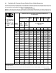
MAXIMUM CABLE CAPACITY BASED ON TEMPERATURE RISE CABLE AMPS 8 60 6 90 4 120 2 240 1 300 1/0 360 2/0 450 3/0 540 640 4/0 710 (2) 2/0 780 (2) 3/0 860 (2) 4/0 940 (2) 4/0 1090 (3) 3/0 1220 (3) 4/0 1340 (4) 4/0 1450 (4) 4/0 900 MCM 1540 1000 MCM 1630 Reference Line AMPERES 2000 VOLTS LOSS IN CABLES 25 1500 TOTAL LENGTH OF CABLES IN FEET 20 1000 30 40 50 900 800 700 100 600 200 500 300 400 500 600 400 800 300 1000 1200 1400 1600 1800 2000 250 CABLE SIZE AWG 8 7 6 5 4 3 2 1 1/0 2/0 3/0 4/0 (2) 2/0 (2
B. Example 2 The welding current will be 400 amperes DC. The total lead length is 400 feet. The weld cable available is 4/0. Draw a straight line from 400 amperes through 400 feet and intersect the reference line. Draw a straight line from the reference intersection through 4/0 cable. The result is a 7.8 volt loss which is above the 4 volt loss recommended. The solution: Use two 4/0 cables in parallel for the work lead and electrode lead. The 7.8 volt loss can be halved by doubling up the cables.
Notes 004 859 Page 9
3-4.
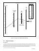
1 Tools Needed: 2 3 4 5 Transformer/Rectifier Welding Power Source Inverter Welding Power Source Engine-Driven Welder/Generator AC/DC Transformer/Rectifier Welding Power Source Weld Cable Connect separate cables of adequate size and equal length to the weld output terminals. 6 Junction Where the weld cables are joined, be sure connecting hardware is adequate for expected amperage and that the junction is properly insulated.
3-5. Paralleling AC Constant Current Transformer-Type Power Sources AC transformer-type power sources can be paralleled for increased amperage demands; however, additional precautions must be taken. The following procedure is recommended: 1. Connect primary wiring of suitable size from each power source to the same phase in the main disconnect switch box.
SECTION 4 − OTHER EQUIPMENT 4-1. Paralleling DC Constant Voltage Power Sources (Not Recommended) It is very difficult to balance these machines as they will only balance in a very narrow band of operation; therefore, paralleling is not typically recommended. 4-2. Paralleling Brush Commutator Design Engine Driven Welder/Generators Or Motor Generators (Not Recommended) The amperage output of these machines must be exactly balanced, otherwise, one power source tries to drive the other.
Owner’s Record Please complete and retain with your personal records. Model Name Serial/Style Number Purchase Date (Date which equipment was delivered to original customer.) Distributor Address City State Zip For Service Contact a DISTRIBUTOR or SERVICE AGENCY near you. Always provide Model Name and Serial/Style Number. Contact your Distributor for: Welding Supplies and Consumables Options and Accessories Personal Safety Equipment Service and Repair Miller Electric Mfg. Co.