AV8 Preamp Processor Préamplificateur-processeur AV8 Vorverstärker/Prozessor AV8 AV8 Voorversterker Processor
Safety guidelines CAUTION ATTENTION RISK OF ELECTRIC SHOCK DO NOT OPEN RISQUE DE CHOC ELECTRIQUE NE PAS OUVRIR 8. Cleaning Unplug the unit from the mains supply before cleaning. The case should normally only require a wipe with a soft, damp, lintfree cloth. Do not use paint thinners or other chemical solvents for cleaning. CAUTION:To reduce the risk of electric shock, do not remove cover (or back). No user serviceable parts inside. Refer servicing to qualified service personnel.
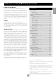
USING THIS HANDBOOK CONTENTS Thank you for purchasing the Arcam FMJ AV8 Preamp Processor. This handbook has been designed to give you all the information you need to install, connect, set up and use the Arcam FMJ AV8 Preamp Processor. The remote control handset supplied with the equipment is also described. Safety guidelines ..........................................................................E-2 Safety instructions ..............................................................................
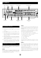
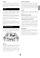
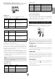
Installation Control connections Serial control Component video connections Digital audio inputs Composite & S-video connections Digital output REMOTE OUT DIGITAL INPUTS IN LOCAL DVD AV Y/G TAPE 1 HIGH QUALITY VIDEO U/B V/R Y/G 2 U/B VIDEO V/R ZONE 2 RS232 CONTROL VIDEO TRIGGERS 2 1 MONITOR OUT TAPE VCR IN VCR OUT AV SAT DVD GND MM 12V IN TRIGGER ZONE 2 50/60Hz 100–240VAC~ MAX 40VA LEFT OUT TUNER CENTRE CD VCR SUB 2 L SURR SAT LS BACK Y/G U/B LEFT CENTRE OUT V/R
FRONT LEFT AND RIGHT The inputs are named to make it easier to reference when connecting e.g., a DVD or VCR, but they all have the same input circuit, so there is no reason why you should not connect a different device to any of the inputs. For example, if you had two DVD players and the AV input was not being used, then the second DVD player can be connected to the AV input.
DIGITAL AUDIO INPUTS AUDIO CONNECTIONS bp DVD, bq AV, br TAPE, bs TUNER, bt CD, ck VCR, cl SAT. Connect these inputs to the digital ouputs of your available source equipment. Take care to place the audio cables as far from any power supply cabling as is practically possible to reduce hum and noise problems.
ANALOGUE PREAMPLIFIER OUTPUTS A receiver compatible with this connector is available from Xantech (part no. 291-10). Please contact a Xantech registered dealer for this part, as ARCAM do not stock them. See www.xantech.com for more information. All these analogue outputs are buffered, have a low output impedance and are at line level. They are able to drive long cables or several inputs in parallel if required. The 3.
VCR OUT. Connect this to the S-video input of your video recorder. fm CONTROL CONNECTIONS fl TAPE. If you are using the tape loop for a second VCR then connect gl gn the S-video from the VCR to this input. HIGH QUALITY (COMPONENT) VIDEO CONNECTIONS Y/G U/B V/R Y/G 2 U/B GROUND LIFT (IN) gm go gq gn IN LOCAL.
have different functions depending on how the ‘Video Status’ has been set (Screen Ctrl or SCART) in the ‘General Settings’ menu. ZONE 2 VIDEO TRIGGERS 2 1 MONITOR OUT 1/RGB 2/S-VIDEO PROG Voltage Video source trigger * Any video source selected = 12V No video source selected = 0V Ring Video source trigger * Any video source selected = 12V No video source selected = 0V Sleeve Ground 0V Notes on Screen Ctrl mode SCART mode In Screen Ctrl mode, the video triggers behave differently.
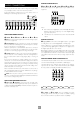
Configuring the AV8 NAVIGATING USING THE REMOTE CONTROL The AV8 ‘Setup Menu’ has six ‘Basic’ and five ‘Advanced’ menu screens which take you through the configuration process. The ‘Basic’ menus enable you to match your AV8 to your speakers.The ‘Advanced’ menus allow you to optimise the operation of your system. Screen shots of these menus are shown in shaded boxes on the following pages. There are two ways to navigate through the Setup menus using the remote control.
1 – GENERAL SETTINGS: 1 - General Settings NOTE: The ‘Sync on Green’ menu option is not selectable when ‘Component’ is selected as the HQ video type. Volume Display: Normal 0-72 Max Volume: +72 Max On Volume: +20 Delay units: OSD Mode: Video Status: HQ Video: Sync On Green: 2 – SPEAKER SIZES Imperial Mixed SCART RGB Off The size and number of loudspeakers are defined on this page of the OSD. 2 - Speaker Sizes Volume display: Allows you to select how volume is displayed.
4 – LEVEL SETTINGS 5.1 Rear speakers defines how the speakers in a full ‘7.1’ installation handle 5.1 decoded sources. 4 - Level Settings Test Tone Cycle: Manual Front L: ---I--- +0dB Centre: ---I--- +0dB Front R: ---I--- +0dB Surr. R: ---I--- +0dB Surr. BR: Not Present Surr. BL: Not Present Surr. L: ---I--- +0dB Subwoofer: ---I--- +0dB Select Speaker for Tone Surr L/R redirects 5.1 surround signal to the surround left and right speakers.
Large+Sub Pure stereo fed to left and right and extracted bass is sent to the subwoofer. Manual The AV8 will not select THX Surr. EX automatically. It can however be selected manually by pressing the THX button. Sat+Sub Use this setting if you have ‘Small’ satellite left and right speakers. Full bass management is used in analogue stereo so that analogue sources are fed to the DSP where the bass is filtered off left and right and redirected to the subwoofer.
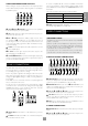
source at the same time – for example, you can listen to radio while watching TV for a sports simulcast. Audio and Video: Applies to the audio and video assignments set up in the ‘Main Menu Screen 1’. ADVANCED SETUP ADV 1 – SPEAKER EQ. If set to Separate, then audio and video signals for video sources can be separately assigned (e.g., DVD sound with video from a satellite receiver). Once assigned separate, audio and video remain separate. Adv 1 - Speaker Eq.
ADV 5 – INPUT TRIMS Adv 4 - Zone 2 Settings Adv 5 - Input Trims Max Vol 20-72: Fix Vol: Max On Vol 0-72: Zone 1 Standby: Zone 2 Standby: Local OSD: Zone 1 Control: Access: Aux: DVD: Sat: AV: VCR: Tape: CD: Tuner: DVD-A: 72 No 20 Local Only Local Only On Yes All Reference Reference Reference Reference Reference Reference Reference Reference Reference 2V 2V 2V 2V 2V 2V 2V 2V 2V Max Vol 20–72: Limits the maximum volume setting for zone 2.
SAVING SETTINGS AND EXITING SETUP Save Settings No Save - Return to index Save as:Preset 1* Preset 2 Preset 3 Preset 4 Preset 5 Press OK to edit- OK to save All the settings you have made on the previous screens can be saved as a user profile and stored as one of five ‘Presets’. A choice of setup presets caters for different events such as movies or sport, and for different user preferences.
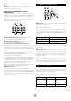
Front panel controls bp 2 3 4 bo English 1 THX SURROUND EX Vol: An. PLII +8 AV8 PREAMP PROCESSOR To n e Movie THX DISPLAY 5 EFFECT MODE MENU OK 6 7 8 DVD SAT AV VCR PHONO/AUX bk 9 CD TUNER TAPE DVD A DIRECT MUTE bl bm POWER bn Remote control receiver. This is positioned behind the FMJ badge. Ensure the receiver is in a clear line of sight from the remote control for operation. If this is not possible, use a separate sensor connected to the IR input on the rear panel.
Remote control The CR80 remote control is a multi-function unit that controls the AV8 and up to seven other devices. The instructions on this page only refer to the control of the Arcam FMJ AV8. For information on using the remote control for other devices, and a full list of features, see the instruction booklet supplied with the CR80. Device selection IMPORTANT: Press the ‘AMP’ button first to operate the AV8.
INTRODUCTION The processing mode and Stereo Direct functions are remembered and recalled for each input. The digital input and high quality video input associated with each source may be customised in the setup procedure. For information display we recommend you use the OSD on your TV/screen whenever possible. However all key information is also duplicated one line at a time on the front panel display of the AV8.
For example, if ‘Record to VCR’ is set to Source and you want to record the SAT input: To listen to zone 2 using the headphones: Call up ‘Main Menu Screen 1’ by pressing the MENU button. Select the SAT input then put your VCR into record pause so that Navigate to screen 3 of the Main Menu by pressing the4 button it will monitor its input. Press the on the remote, or by turning the volume knob on the front panel.
INFO Three Main Menu screens allow day-to-day changes to be made to the way the AV8 operates. Examples include adjusting the tone control for a particular input, recording one source while listening to another or configuring the headphone output. SYN Delays may be introduced into the video signal by external video processing equipment which causes a mismatch between the audio and video timing. You will notice this by speech sound being out of synchronisation with the lip movements in the video.
Stereo Direct: If Stereo direct is Off, the AV8 functions in its normal way. video processing is used in the system for line doubling or progressive scan video. The range of lip sync delay is -5 to 220 milliseconds. If stereo direct is On, the AV8 uses the analogue input signal for the source, bypassing the digital circuitry. In this mode, the AV8 functions like an analogue preamp: it also shuts down all the unused digital circuitry for optimum stereo performance.
MAIN MENU SCREEN 3 USING ZONE 2 This page refers to zone 2 functions. These are required if your system is installed to send audio and video to a separate ‘zone 2’ room, or you wish to make use of the zone 2 headphone facility. Zone 2 provides the option for the occupants of the master bedroom, children’s room or kitchen to view or listen to a different source at a different volume level from the main zone (zone 1).
Surround modes If you would rather listen to a 2.0 or 2.1 bitstream in ordinary stereo (with or without a subwoofer), press MODE to cycle through to the Stereo mix mode (e.g., Dolby Digital 2/0.0 on the display). However, if the source becomes a multichannel bitstream (e.g., 5.1) again, the AV8 will recall Stereo mix mode and therefore output a Stereo Downmix of the multichannel signal. Full surround output can be re-achieved by pressing MODE to cycle through to the surround mode encoded on the disc.
DTS NEO:6 Cinema: A movie mode designed to reproduce a movie theatre environment with natural steering to all available surround speakers from a two-channel stereo or matrix encoded source. DTS-ES 6.1 Matrix: This is a 6.1 channel format based on DTS 5.1. It has the sixth channel matrix encoded into the surround left and surround right channels. The sixth channel is a surround centre channel and is directed to the surround back left and surround back right speakers.
THX Surround EX and Surround ES ABOUT THX® CINEMA PROCESSING Surround EX is a joint development of Dolby Laboratories and the THX division of Lucasfilm Ltd. In a movie theatre, film soundtracks that have been encoded with Surround EX technology are able to reproduce an extra channel which has been added during the mixing of the programme. This channel, called surround back, places sounds behind the listener in addition to the front left, centre, front right, surround left, surround right and LFE channels.
There are no lights on the unit: OSD Display is pink/red Check that: If a component video signal is fed into the AV8 when the ‘HQ Video’ setting is set to RGB you will have a pink/red OSD. the power cord is plugged into the AV8 and the mains socket To correct this you must set the ‘HQ Video’ line on the General Settings menu to ‘Component’. outlet it is plugged into is switched on. the power button is pressed in.
Unable to select Dolby Digital or DTS decoding modes: Volume is always too loud when I turn the system on for the main zone or zone 2: The AV8 can only apply Dolby Digital and DTS decoding to sources which have been encoded in the same format. Check: Check that: the ‘Max On Volume’ line of ‘General Settings’ or ‘Zone 2 Settings’ pages in the Setup Menu. They will need adjusting to a lower level. a digital source is selected and connected. the source is playing appropriately encoded material.
Unable to adjust bass and treble controls: Bass and treble is not available in THX mode. For Analogue Stereo and Digital Stereo modes, check that the ‘Auto Stereo Tone Bypass’ line of ‘Speaker Eq’ in the Setup Menu is set to No. Unable to adjust balance control: English Balance is not available in THX mode. Digital signal drops out when other electrical appliances turn on (heating, fridge, freezer, etc.
Technical specifications Audio Line input sensitivity (set to Reference) 2V rms Input impedance 10kΩ Preamp output level (nominal) 2V rms Output impedance 25Ω Signal/noise ratio (unwtd 20Hz–20kHz) – analogue >100dB Signal/noise ratio (unwtd 20Hz–20kHz) – digital (24-bit) >98dB THD+N – analogue 0.0012% THD+N – digital (24-bit) 0.
RADIO INTERFERENCE LOCKING THE SETUP MENU The AV8 is a digital audio device which have been designed to very high standards of electromagnetic compatibility. With the facility for up to five preset setups, and the ability to temporarily trim many settings, there should little need to use the Setup Menus once the system is fully installed. Many of the AV8 settings in the Setup Menus require specialist knowledge and measurement.
SCART CONNECTIONS These pinouts describe the signal connections between the AV8 and your display device input.
The following information is supplied for owners of advanced programmable remote controls, such as the Philips ‘Pronto’ and similar devices, where it is possible to program remote codes directly into the device. The coding system for the AV8 is based on the Philips RC-5 standard. The main system control uses RC-5 system code ‘16’, so for example, to program in a ‘Standby’ command, use the command ‘16-124’.
QUERY COMMANDS AV8 SERIAL PROGRAMMING INTERFACE The current values of a small subset of settings may be queried, by preceding the command with a ?. For example, to query the mute status of zone 2, use: INTRODUCTION ?Z2MUT This section of the document details the serial command set of the AV8 software.
Command Parameters Description Response PWR ?zPWR Query Power State zPWRx, where z is the zone parameter you supply. MUT ?zMUT Query Mute State zMUTx, where z is the zone parameter you supply. EFF ?EFF Query Effect Mode EFFy, where y may have the values 0 to 7, as follows: THX ?THX Query THX Mode DEC ?DEC Query Decode/Downmix Mode 0 = off, 1 = music, 2 = party, 3 = club, 4 = hall, 5 = sport, 6 = church, 7 = next effect.
GENERAL OPERATION COMMANDS Command Parameters Description PWR ?zPWRx Power on/off MUT ?zMUTx Mute on/off FAN zFANx Force Analogue EFF ?EFFy Effect Mode Selection Parameter values y may have the values 0 to 7, as follows: 0 = off, 1 = music, 2 = party, 3 = club, 4 = hall, 5 = sport, 6 = church, 7 = next effect. THX ?THXy THX Mode Selection y may have the values 0 to 4, as follows: 0 = Off, 1 = THX Cinema, 2 = THX Ultra2 Cinema, 3 = THX MusicMode, 4 = THX SurrEX.
SETUP COMMANDS – BASIC Basic General Command Parameters Description Parameter values VDS VDSy Volume Display y may have the values 0 to 2, as follows: MXV zMXVy Max Volume y may have a value in the range -33 to +19: -33 = –33dB +19 = +19dB MXO zMXOy Max On Volume y may have a value in the range -53 to +19: -53 = –53dB +19 = +19dB DYU DYUy OMD OMDy OSD Mode VST VSTy Video Status HQV HQVy HQ Video SYG SYGx Sync On Green Delay Units y may have the values 0 to 2, as follows: 0 = I
Basic Sub Command Parameters Description Parameter values CRF CRFy Crossover Frequency y may have a value in the range 0 to 11: 0 = 40Hz 11 = 150Hz (in 10Hz steps) STM STMy Stereo Mode y may have the values 0 to 2, as follows: 0 = Large+Sub, 1 = Sat+Sub, 2 = Large. LFE LFEy LFE Level y may have a value in the range -10 to 0: -10 = –10dB 0 = 0dB DLF DLFy DTS LFE Gain SST SSTy Sub Stereo y may have the values 0 to 1, as follows: 0 = 0dB Normal, 1 = –10dB.
SETUP COMMANDS – ADVANCED Command Parameters Description Parameter values BAS BASsy Bass Levels y may have a value in the range -6 to +6: -6 = –6dB +6 = +6dB TRB TRBsy Treble Levels y may have a value in the range -6 to +6: -6 = –6dB +6 = +6dB STB STBx Auto Stereo Tone Bypass Advanced Video Command Parameters Description OSD zOSDx OSD VIA VIAi Video Input AUX VIC VICi Video Input CD VIT VITi Video Input Tape VIM VIMi Video Input Multichannel ANV ANVy Audio and Video HQS
Engineering Settings Command Parameters Description Parameter values RC5 zRC5y RC5 System Code y may have the values 0 to 5, as follows: SCM SCMx Scrolling Message SCT SCTyn Scrolling Text Select 0 = RC5 System Code 16, 1= RC5 System Code 19. EPE y may have a value in the range 0 to 8. If y = 0, then n can be a string of your choice. If no string is given, the default is used.
UTILITY SOFTWARE AV8 PROGRAMMER English The AV8 programmer utility allows future software upgrades to be installed and allows backup and restoration of the unit’s settings via the RS232 port on the back of the AV8. The following equipment is required: IBM PC compatible computer running Windows 98 or later. Software – ARCAM AV8 Programmer utility (included on the AV8 CD-ROM). Lead – RS232 9-way female D-type to 9-way female D-type (i.e., a null modem).
Guarantee WORLDWIDE GUARANTEE For further details contact Arcam at: This entitles you to have the unit repaired free of charge, during the first two years after purchase, at any authorised Arcam distributor provided that it was originally purchased from an authorised Arcam dealer or distributor.