HANDBOOK Arcam AVR200 surround sound receiver Ampli-tuner audiovidéo Arcam AVR200 Arcam AVR200 Surround-Sound-Empfänger AVR 2 0 0 E nglis h Fra nça is D eut s ch
Safety guidelines Safety instructions This product is designed and manufactured to meet strict quality and safety standards. However, you should be aware of the following installation and operation precautions: 1. Take heed of warnings and instructions You should read all the safety and operating instructions before operating this appliance. Retain this handbook for future reference and adhere to all warnings in the handbook or on the appliance. 2.
This handbook has been designed to give you all the information you need to install, connect, set up and use the Arcam AVR200 surround sound receiver. The remote control handset supplied with the equipment is also described. It may be that the AVR200 has been installed and set up as part of your system installation by a qualified Arcam dealer. In this case, you may wish to skip the sections of this handbook dealing with installation and setting up the unit.
Installation Installation starts with positioning the unit where it can operate effectively. To use the radio receiver, you will need to install an FM and/or an AM aerial. AM aerial Other input signals – from CD, MD, tape, DAT, VCR, DVD, games console or satellite receiver – will need to be connected to sockets on the AVR200’s back panel. An external AM loop aerial is supplied as an accessory with the AVR200.
E ng l i s h Connecting inputs AUDIO PRE-OUT R L ANTENNA FRONT AM (N.AM)10K AM STEP FRONT MONITOR OUT S-VIDEO VIDEO R (EU) 9K R SURROUND L + R AUDIO L SURR GND CENTRE L + GROUND GROUND LIFT LOUDSPEAKER OUTPUTS OUT AUX CENTRE TAPE R L SUB WOOFER – – OUT 5.
GROUND LIFT switch If your system only takes audio sources from CD or DVD, set this switch to ‘GROUND’. In more complex setups which involve satellite inputs or radio aerials, grounding the unit may actually increase the level of background hum or buzz in the loudspeakers, in which case set the switch to ‘GROUND LIFT’. REMOTE CONTROL INPUT This input is connected to the output of an infrared receiver. The remote control input is usually used in custom installations.
E ng l i s h Connecting outputs Connecting to other equipment Connecting to a power supply MONITOR OUT Wrong plug? Both composite and S-video monitor outputs are provided for connection to the ‘Video line in’ of your TV, monitor, or projector. If you have both Composite and S-video inputs connected to your AVR200 you need only connect the S-VIDEO Monitor Output to your TV (provided that your TV accepts an S-video input).
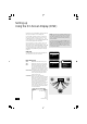
Setting up Using the On Screen Display (OSD) The easiest way to set up the AVR200’s multi-channel audio and video options is through its On Screen Display (OSD). To enter the OSD, ensure that you have a TV connected and press any of the arrows on the remote control’s cursor pad. • • and To navigate from the first (i.e. Setup) page, use the arrows to highlight a line. To enter a highlighted page, press OK. To leave the OSD, highlight ‘EXIT’ and press OK.
(Dolby Pro Logic II Music Mode only) Allows the gradual adjustment of the soundfield either towards the front or the rear. This can help achieve the desired balance from all the speakers with certain recordings that may contain either too much or too little spatial effect. Step ‘0’ is the recommended setting, which has no effect on the sound. Steps ‘+1’, ‘+2’ and ‘+3’ gradually move the sound forward, and steps ‘–1’, ‘–2’ and ‘–3’ move the sound towards the surrounds.
To calculate these delay times, first measure (or estimate) the distances from the listening position to the front, centre and rear speakers. Keep a record of these distances by entering them under the heading ‘Your measurement’ in the table provided. The centre channel delay is calculated by subtracting the centre channel distance from the front left (or right) distance. The difference represents the CENTRE delay time. front left e.g.
The size and number of loudspeakers are defined on this page of the OSD. – – – – A ‘LARGE’ speaker is one that is capable of handling a full range signal (i.e. 20Hz–20kHz). A ‘SMALL’ speaker is one that is not capable of reproducing a deep bass signal (i.e. below 100Hz), for example a satellite speaker. ‘ON’ is used when a speaker is present and active and receives the intended audio information. ‘OFF’ is used when a speaker is absent or inactive.
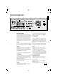
Using the AVR200 Front panel controls VOLUME A/V SURROUND SOUND RECEIVER RDS INFO FM MUTE/ MONO AVR200 STORE PRESET/ TUNE DOLBY PL II MUSIC DOWN/UP SPEAKERS FM MUTE VIDEO 1 TUNED FM STEREO PRESET MHz PHONES SAT DVD VCR AUX EXT 5.1 SURROUND MODE TAPE MONITOR CD FM AM BASS DIRECT TREBLE POWER POWER Dolby Digital, DTS Press the POWER button to turn the AVR200 on. The status LED changes to green on powering up and the display shows the active input.
TAPE MONITOR E ng l i s h The TAPE MONITOR button selects the audio output from a cassette deck connected to the TAPE IN phono sockets of the AVR200. It also enables you to monitor a recording being made on a 3-head cassette deck. Tape monitor status is shown in red on the display. When the tape monitor is selected, pressing other source buttons changes the signal sent to the recorder. NOTE: TAPE MONITOR is a latching button: you will need to press it again before selecting another source for listening.
Using the tuner The AVR200’s radio tuner can be controlled from the upper row of front panel buttons (see diagram, below) or from the remote control handset (see ‘Using the remote control’). RDS INFO FM MUTE/ MONO PRESET/ TUNE STORE DOWN/UP DOLBY PL II MUSIC SPEAKERS FM MUTE VIDEO 1 TUNED FM STEREO PRESET MHz Tuning to a station RDS: Radio Data System Pressing the PRESET/TUNE button toggles between the two tuning modes of the unit – ‘Preset’ or ‘Tune’.
E ng l i s h Using the remote control CR-340 Remote Control The CR-340 remote control gives access to all functions available on the front panel, plus some additional functions only available from the remote. It also has controls to operate Arcam CD and DVD players. CD/DVD lights These indicate the function of the CD/DVD button at the bottom of the control. They are not related to any function on the AVR200. The LED only stays on for 15 seconds to conserve battery life.
Reference Bi-wiring and bi-amping loudspeakers Before you start Bi-amping your system WARNING: Do not make any connections to your amplifier while it is switched on or connected to the mains supply. Before switching on please check all connections thoroughly, making sure bare wires or cables are not touching the amplifier in the wrong places (which could cause short circuits) and you have connected positive (+) to positive and negative (–) to negative.
E ng l i s h Troubleshooting The following table should help you diagnose most problems that may arise when using the AVR200. Problem Cause Solution No audio 1. Power Lead unplugged or not switched on 2. In stand by mode 3. Mute on 4. Tape monitor selected 1. Check mains lead is connected to AVR200 and that the wall switch is on 2. Press the POWER/STANDBY button on remote handset 3. Switch mute off 4. Press the TAPE MONITOR button 1. 2. 3. 4.
Technical specifications AMPLIFIER SPECIFICATION RADIO SPECIFICATION Output power (20Hz–20kHz at 0.5%THD) 8Ω, five channels 70W 8Ω, two channels 90W 8Ω, single channel 100W Harmonic distortion, 1W, 8Ω at 1kHz 0.02% typical Left/right crosstalk 60dB at 1kHz Frequency response ±1.0dB 20Hz to 20kHz FM section 30 preset stations available RDS Station Identification, Radio Data Display FM tuning range 87.
Worldwide Guarantee This entitles you to have the unit repaired free of charge, during the first two years after purchase, at any authorised Arcam distributor provided that it was originally purchased from an authorised Arcam dealer or distributor.