
Specifications
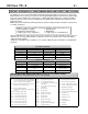


Optima 70 - 2 24
ELECTRICAL CONNECTIONS, FAN SYSTEM
WARNING: Before starting make certain the power supply is turned off.
The Optima 70 comes complete with a temperature activated fan and rheostat installed and
wired to an internal junction box. The heat sensor is factory set to close the circuit to the fan
speed control at 110
0
F (43
0
C) and will turn off the fan when the temperature falls below 90
0
F
(32
0
C).
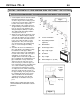
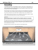
Have a qualified electrician run a 120VAC supply line to the lower left side of the fireplace
before installing the appliance. There should be 18” (460mm) of the supply line free for ease of
connection to the appliance. Connect the electrical supply line to the appliance at the same
time the gas line is being connected to the appliance.
NOTE: This appliance, when installed, must be electrically grounded in accordance with local
codes or, in the absence of local codes, with the National Electrical Code, ANSI/NFPA 70, or
the Canadian Electrical code, CSA C22.1.
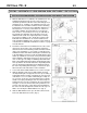
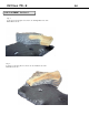
Open the bottom (louver) grill and undo the 2 screws holding the control panel. Run the line into
the left side of the appliance through the hole in the rear of the junction box and hold with a
standard 7/8” (22 mm) clamp. Connect the (black) supply conductor to the free black conductor
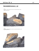
from the speed controller with a marrette type wire connector. Connect the ‘neutral’ white
supply conductor to the free white conductor from the fan with a marrette type wire connector.
Connect the ‘ground’ (green or bare) conductor to the ground screw in the junction box.
Replace the junction box cover and control panel and fasten with the 2 screws. A BX connector
or other suitable approved wiring strain relief must be installed on the junction box.
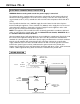
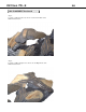
WIRING DIAGRAM
MO
SPEED
CONTROL
110F (43ºC) N.O.
THERMAL SNAP
SWITCH
CONVECTION BLOWER
LINE
GROUND
NEUTRAL
To Fan Mount
(with star washer)
120 VAC
white
black
SPEED
CONTROL
LINE
GROUND
NEUTRAL
110F (43ºC) N.O.
THERMAL SNAP
SWITCH
CONVECTION BLOWER
black white black
green