User Manual IP™-Six 2-Channel Power Amplifier
Intended to alert the user to the presence of uninsulated “dangerous voltage” within the product’s enclosure that may be of sufficient magnitude to constitute a risk of electric shock to persons. Intended to alert the user of the presence of important operating and maintenance (servicing) instructions in the literature accompanying the product. CAUTION: Risk of electrical shock — DO NOT OPEN! CAUTION: To reduce the risk of electric shock, do not remove cover. No user serviceable parts inside.
IMPORTANT SAFETY INSTRUCTIONS WARNING: When using electrical products, basic cautions should always be followed, including the following: 1. 2. 3. 4. 5. 6. 7. 8. 9. 10. 11. 12. 13. 14. 15. 16. 17. 18. 19. Read these instructions. Keep these instructions. Heed all warnings. Follow all instructions. Do not use this apparatus near water. Clean only with a dry cloth. Do not block any of the ventilation openings. Install in accordance with manufacturer’s instructions.
WICHTIGE SICHERHEITSHINWEISE ACHTUNG: Beim Einsatz von Elektrogeräten müssen u.a. grundlegende Vorsichtsmaßnahmen befolgt werden: 1. Lesen Sie sich diese Anweisungen durch. 2. Bewahren Sie diese Anweisungen auf. 3. Beachten Sie alle Warnungen. 4. Befolgen Sie alle Anweisungen. 5. Setzen Sie dieses Gerät nicht in der Nähe von Wasser ein. 6. Reinigen Sie es nur mit einem trockenen Tuch. 7. Blockieren Sie keine der Lüftungsöffnungen. Führen Sie die Installation gemäß den Anweisungen des Herstellers durch. 8.
INSTRUCTIONS IMPORTANTES DE SECURITE ATTENTION: L’utilisation de tout appareil électrique doit être soumise aux precautions d’usage incluant: 1. 2. 3. 4. 5. 6. 7. 8. 9. 10. 11. 12. 13. 14. 15. 16. 17. 18. 19. Lire ces instructions. Gardez ce manuel pour de futures références. Prétez attention aux messages de précautions de ce manuel. Suivez ces instructions. N’utilisez pas cette unité proche de plans d’eau. N’utilisez qu’un tissu sec pour le nettoyage de votre unité.
INSTRUCCIONES IMPORTANTES PARA SU SEGURIDAD CUIDADO: Cuando use productos electrónicos, debe tomar precauciones básicas, incluyendo las siguientes: 1. Lea estas instrucciones. 2. 3. 4. 5. 6. 7. 8. 9. 10. 11. 12. 13. 14. 15. 16. 17. 18. 19. Guarde estas instrucciones. Haga caso de todos los consejos. Siga todas las instrucciones. No usar este aparato cerca del agua. Limpiar solamente con una tela seca. No bloquear ninguna de las salidas de ventilación.
IMPORTANT PRECAUTIONS This symbol is used to alert the user to the presence of important operating and maintenance (servicing) instructions in the literature accompanying the product. This symbol is used to alert the user to the presence of “dangerous voltage” within the product enclosure that be of sufficient magnitude to constitute a risk of electric shock to persons. 8. Have gain controls on amplifiers turned down during power-up to prevent speaker damage if there are high signal levels at the inputs.
ENGLISH IP™-Six Power Amplifier Introduction Congratulations on your purchase of a Peavey Architectural Acoustics IP-Six power amplifier. Please read this manual carefully (especially the “Important Precautions” section located inside the front cover) as it contains information vital to the safe operation of the amplifier. Also, please fill out and return the enclosed product registration card.
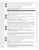
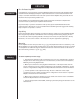
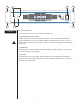
1 2 4 1 ON Ch A Ch B CLIP - S I X RCHITECTURAL COUSTICS INDUSTRIAL POWER AMPLIFIER STATUS TM by POWER 1 Front Panel 3 1 (1) Rack Mounting Ears Two mounting holes are provided on each front mounting ear. (2) AC Power Switch/Circuit Breaker A power switch-and-circuit breaker combination switch is on the front panel. With the switch pushed toward the up position, the amplifier is ON. If the switch/breaker continues to trip, the amplifier needs servicing.
3 4 CAUTION 120VAC ~ 60Hz 550 Watts RISK OF ELECTRIC SHOCK DO NOT OPEN AVIS: RISQUE DE CHOC ÉLECTRIQUE-NE PAS OUVRIR WARNING: TO REDUCE THE RISK OF FIRE OR Outputs RCHITECTURAL 400W/Ch. @ 2 Ohms Ch B Inputs COUSTICS Ch A ELECTRIC SHOCK, THIS APPARATUS SHOULD NOT BE EXPOSED TO RAIN OR MOISTURE AND OBJECTS FILLED WITH LIQUIDS, SUCH AS VASES, SHOULD NOT BE PLACED ON THIS APPARATUS.
Operation AC Mains Circuit Size Requirements Power requirements for the IP™-Six amplifier are rated at “idle”, 1/8 power (“typical” music conditions), 1/3 power and maximum rated power. The maximum power current draw rating is limited by the amplifier’s circuit breaker. Consult the specification sheet for the current that each amplifier will demand. AC mains voltage must be the same as that indicated on the back of the amplifier.
Operation Signal Mode Configuration The IP™-Six amplifier is configured for Two-Channel (Stereo), Bridged Mode or Parallel Mode operation at the input connector. To send the same signal to both channels (Parallel Mode), connect the input signal to channel A via the input connector. Run jumpers from the positive and negative terminals of channel A’s input connector to the respective terminals of channel B. Both channels then share channel A’s input signal, but will operate independently.
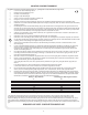
CONNECTIONS Speaker Output Connections Speakers are connected using the output barrier strip connectors. Spade lugs, ring tongues or bare wire may be connected to the output barrier strip elements. The barrier strip can accommodate up to a 10gauge wire per terminal. Make sure the amplifier is turned off before you change any output connections or jumpers. Consult the Wire Gauge Chart (page 14) to find a suitable wire gauge to minimize losses of power in the speaker cables.
WIRE GAUGE CHART Stranded Cable Lgth. (ft.) Wire Gauge (AWG) Power Loss (8 ohm load) Power Loss (4 ohm load) Power Loss (2 ohm load) 5 18 16 14 12 10 0.81% 0.51 0.32 0.20 0.128 1.61% 1.02 0.64 0.40 0.25 3.2% 2.0 1.28 0.80 0.51 10 18 16 14 12 10 1.61% 1.02 0.64 0.40 0.25 3.2% 2.0 1.28 0.80 0.51 6.2% 4.0 2.5 1.60 1.01 40 18 16 14 12 10 8 6.2% 4.0 2.5 1.60 1.01 0.60 11.9% 7.7 5.0 3.2 2.0 1.20 22% 14.6 9.6 6.2 4.0 2.4 18 16 14 12 10 8 11.9% 7.7 5.0 3.2 2.0 1.20 22% 14.6 9.6 6.2 4.0 2.
PROTECTION FEATURES The IP™-Six incorporates protection features derived from Peavey’s commitment to reliability. These comprehensive protection circuits will protect your amplifier in the real world. Clip Limiting At the amplifier’s full power, or clipping point, the channel gain will automatically be reduced, guarding the loudspeakers against damaging high power and continuous square waves that would otherwise be produced. This is indicated by illumination of the Clip LED.
IP™-Six SPECIFICATIONS Rated Power 4 ohms bridge 825 watts @ 1 kHz <0.025% THD Rated Power 8 ohms bridge/70 volts 612 watts @ 1 kHz Sine Wave <0.025% THD Program Power 8 ohms bridge/70 volts 800 watts Rated Power 2 x 2 ohms 400 watts per channel @ 1 kHz <0.025% THD both channels driven Rated Power 2 x 4 ohms 300 watts per channel @ 1 kHz <0.02% THD both channels driven Rated Power 2 x 8 ohms 180 watts per channel @ 1 kHz <0.
IP™-Six SPECIFICATIONS Input Impedance 15k ohms, balanced Hum and Noise > -110dB, “A” weighted referenced to rated 4 ohm power Crosstalk > -70dB, “A” weighted referenced to rated 4 ohm power Current Draw @ 1/8 power 465 watts @ 2 ohms, 320 watts @ 4 ohms, 210 watts @ 8 ohms Current Draw @ 1/3 power 996 watts @ 2 ohms, 683 watts @ 4 ohms, 396 watts @ 8 ohms Idle Current Draw 30 watts Max. Current Draw 1752 watts @ 2 ohms, 1158 watts @ 4 ohms, 710 watts @ 8 ohms Thermal Emissions (BTU/hr.
DEUTSCH WICHTIGE SICHERHEITSHINWEISE Dieses Symbol weist den Anwender auf wichtige Informationen zu Betrieb und Wartung in der Begleitliteratur des Produkts hin. 8. Drehen Sie vor dem Einschalten die Gain-Regler der Verstärker herunter, um eine Beschädigung der Lautsprecher zu vermeiden, falls an den Eingängen hohe Signalpegel vorliegen sollten.
DEUTSCH IP™-Six-Endstufe Einleitung Herzlichen Glückwunsch zum Kauf Ihrer IP-Six-Endstufe von Peavey Architectural Acoustics! Lesen Sie sich diese Bedienungsanleitung (insbesondere den Abschnitt „Wichtige Sicherheitshinweise“ innen auf der Umschlagseite) sorgfältig durch. Sie enthält unerlässliche Informationen zum sicheren Betrieb des Verstärkers. Füllen Sie bitte auch die beiliegende Produktregistrierungskarte aus und senden Sie sie zurück.
1 2 4 1 ON Ch A Ch B CLIP - S I X RCHITECTURAL COUSTICS INDUSTRIAL POWER AMPLIFIER STATUS TM by POWER 1 Vorderseite 3 1 (1) Rack-Montageösen An jeder vorderen Montageöse befinden sich zwei Montagelöcher. (2) Wechselstrom-Netzschalter/Schutzschalter Auf der Vorderseite befindet sich ein kombinierter Netz- bzw. Schutzschalter. Wird der Schalter nach oben gedrückt, ist der Verstärker eingeschaltet (Position ON).
3 4 CAUTION 120VAC ~ 60Hz 550 Watts RISK OF ELECTRIC SHOCK DO NOT OPEN AVIS: RISQUE DE CHOC ÉLECTRIQUE-NE PAS OUVRIR WARNING: TO REDUCE THE RISK OF FIRE OR Outputs RCHITECTURAL 400W/Ch. @ 2 Ohms Ch B Inputs COUSTICS Ch A ELECTRIC SHOCK, THIS APPARATUS SHOULD NOT BE EXPOSED TO RAIN OR MOISTURE AND OBJECTS FILLED WITH LIQUIDS, SUCH AS VASES, SHOULD NOT BE PLACED ON THIS APPARATUS.
Betrieb Erforderliche Werte der Wechselstrom-Netzversorgung Der Leistungsbedarf des IPa-Six-Verstärkers ist auf Blindstrom, 1/8 („typische“ Musikbedingungen), 1/3 Leistung sowie maximale Nennleistung ausgelegt. Der maximale Nennwert der Stromaufnahme wird über den Schutzschalter des Verstärkers begrenzt. Den Leistungsbedarf der jeweiligen Verstärker können Sie den technischen Daten entnehmen. Die Wechselstrom-Netzspannung muss mit den Angaben auf der Rückseite des Geräts übereinstimmen.
Betrieb Konfiguration des Signalmodus Der IP™-Six-Verstärker ist für den Betrieb im Zweikanal- (Stereo-), Bridged- oder Parallel-Modus am Eingangsstecker konfiguriert. Um dasselbe Signal an beide Kanäle zu senden (Parallelmodus), wird das Eingangssignal über die Eingangsbuchse an Kanal A angeschlossen. Danach werden Steckverbindungen von der positiven und negativen Klemme der Eingangsbuchse von Kanal A an die jeweiligen Klemmen von Kanal B angeschlossen.
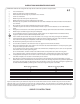
ANSCHLÜSSE Anschlüsse der Lautsprecherausgänge Die Lautsprecher werden über die Stecker der Ausgangsklemmleiste angeschlossen. An die Ausgangsklemmleisten können Greifer, Ringkabelschuhe oder blanker Draht angeschlossen werden. Die Klemmleiste ist für Drähte mit einer Stärke von bis zu 10 pro Klemme (siehe Wire Gauge Chart) ausgelegt. Stellen Sie sicher, dass der Verstärker ausgeschaltet ist, bevor Sie Ausgangsanschlüsse oder Steckverbindungen austauschen.
DRAHTSTÄRKENTABELLE (WIRE GAUGE CHART) Stranded Cable Lgth. (ft.) Wire Gauge (AWG) Power Loss (8 ohm load) Power Loss (4 ohm load) Power Loss (2 ohm load) 5 18 16 14 12 10 0.81% 0.51 0.32 0.20 0.128 1.61% 1.02 0.64 0.40 0.25 3.2% 2.0 1.28 0.80 0.51 10 18 16 14 12 10 1.61% 1.02 0.64 0.40 0.25 3.2% 2.0 1.28 0.80 0.51 6.2% 4.0 2.5 1.60 1.01 40 18 16 14 12 10 8 6.2% 4.0 2.5 1.60 1.01 0.60 11.9% 7.7 5.0 3.2 2.0 1.20 22% 14.6 9.6 6.2 4.0 2.4 18 16 14 12 10 8 11.9% 7.7 5.0 3.2 2.0 1.
SCHUTZFUNKTIONEN Der IP™-Six ist mit Schutzfunktionen ausgestattet, die für Peaveys Verpflichtung zur Zuverlässigkeit sprechen. Diese umfassenden Schutzschaltungen werden Ihren Verstärker auch unter anspruchsvollen Bedingungen schützen. Clip Limiting Bei voller Leistung oder am Clipping-Punkt wird die Kanalverstärkung automatisch verringert, sodass die Lautsprecher vor den starken kontinuierlichen Rechteckwellen geschützt sind, die andernfalls erzeugt werden und Schaden verursachen können.
IP™-Six TECHNISCHE DATEN Nennleistung 4 Ohm gebrückt 825 Watt bei 1 kHz <0,025% Klirrfaktor Nennleistung 8 Ohm gebrückt/70 Volt 612 Watt bei 1 kHz Sinuswelle <0,025% Klirrfaktor Programmleistung 8 Ohm gebrückt/70 Volt 800 Watt Nennleistung 2 x 2 Ohm 400 Watt pro Kanal bei 1 kHz <0,025% Klirrfaktor, beide Kanäle getrieben Nennleistung 2 x 4 Ohm 300 Watt pro Kanal bei 1 kHz <0,02% Klirrfaktor, beide Kanäle getrieben Nennleistung 2 x 8 Ohm 180 Watt pro Kanal bei 1 kHz <0,02% Klirrfaktor, beide Kanäl
IP™-Six TECHNISCHE DATEN Eingangsimpedanz 15 kOhm, symmetriert Brummen und Rauschen > -110 dB, „A“-gewichtet, bezogen auf 4 Ohm Nennleistung Crosstalk > -70 dB, „A“-gewichtet, bezogen auf 4 Ohm Nennleistung Stromaufnahme bei 1/8 Leistung 465 Watt an 2 Ohm, 320 Watt an 4 Ohm, 210 Watt an 8 Ohm Stromaufnahme bei 1/3 Leistung 996 Watt an 2 Ohm, 683 Watt an 4 Ohm, 396 Watt an 8 Ohm Blindstromaufnahme 30 Watt Max.
PRECAUTIONS IMPORTANTES FRANÇAIS Ce symbole est utilisé pour prévenir les utilisateurs de la présence dans ce manuel d’instructions très importantes concernant la réparation et la maintenance de l’appareil. 8. Lors de l’allumage, veuillez positionner les contrôles de gains sur 0 pour prévenir tout dommages aux enceintes du à un niveau de signal trop important. 9. Eteindre et débrancher le courant de l’unité avant d’effectuer les connections. 10.
FRANÇAIS Amplificateur IP™-Six Introduction Félicitations d’avoir choisi un amplificateur de puissance Peavey Architectural Acoustics IP-Six. Veuillez lire ce manuel attentivement ( particulièrement les précautions importantes situées à l’interieur la première page de couverture). Il contient des opérations vitales pour une utilisation de votre matériel en toute sécurité. Par ailleurs, veuillez remplir et retourner la carte de registration jointe.
1 2 4 1 ON Ch A Ch B CLIP - S I X RCHITECTURAL COUSTICS INDUSTRIAL POWER AMPLIFIER STATUS TM by POWER 1 3 1 Panneau avant (1) Oreilles de montage en rack Deux trous sont prévus pour chaque oreille de montage avant. (2) Interrupteur AC/Coupe circuit Un interrupteur combinant une commande de mise sous/hors tension et un coupe circuit se situent sur le panneau avant de votre unité. Lorsque le sélecteur est poussé vers le haut l,amplificateur est sous tension.
3 4 CAUTION 120VAC ~ 60Hz 550 Watts RISK OF ELECTRIC SHOCK DO NOT OPEN AVIS: RISQUE DE CHOC ÉLECTRIQUE-NE PAS OUVRIR WARNING: TO REDUCE THE RISK OF FIRE OR Outputs RCHITECTURAL 400W/Ch. @ 2 Ohms Ch B Inputs COUSTICS Ch A ELECTRIC SHOCK, THIS APPARATUS SHOULD NOT BE EXPOSED TO RAIN OR MOISTURE AND OBJECTS FILLED WITH LIQUIDS, SUCH AS VASES, SHOULD NOT BE PLACED ON THIS APPARATUS.
Opération connecter l’alimentation Les puissances requises pour les amplificateurs de la série IP-Six sont mesurées à 1/8 des capacités (signal musical normal) et à 1/3 des capacités (signal musical fort). La mesure maximale de la consommation électrique n’est limitée que par le coupe circuit du panneau avant. Consutez les spécifications dans la section Appendices pour voir la consommation requise pour chaque amplificateur.
Opération Configuration des modes de signaux L’unité IP™-Six est configurée pour les modes d’opérations suivants: Deux canaux stéréo, Mono mode pont et, mode Parallèle. Pour envoyer le même signal sur les deux canaux (mode parallèle), connecter le signal d’entrée sur le canal A des connecteurs d’entrées. Installer des cavaliers aux bornes positives et négatives de l’entrée A et reliez les respèctivement aux bornes du canal B.
CONNECTIONS Connection des enceintes de sorties Les enceintes se connectent en utilisant les borniers de connecteurs de sortie. Vous pourrez utiliser des connecteurs broches, en anneaux ou des fils dénudés. Les borniers de connection des sorties peut accepter des câbles allant jusqu’à une epaisseur maximale de 10gauge (6mm) par terminal. Assurer vous que l’amplificateur est éteint avant d’effectuer toutes manipulations de connections.
CHARTE DES MESURES DE CABLES Stranded Cable Lgth. (ft.) Wire Gauge (AWG) Power Loss (8 ohm load) Power Loss (4 ohm load) Power Loss (2 ohm load) 5 18 16 14 12 10 0.81% 0.51 0.32 0.20 0.128 1.61% 1.02 0.64 0.40 0.25 3.2% 2.0 1.28 0.80 0.51 10 18 16 14 12 10 1.61% 1.02 0.64 0.40 0.25 3.2% 2.0 1.28 0.80 0.51 6.2% 4.0 2.5 1.60 1.01 40 18 16 14 12 10 8 6.2% 4.0 2.5 1.60 1.01 0.60 11.9% 7.7 5.0 3.2 2.0 1.20 22% 14.6 9.6 6.2 4.0 2.4 18 16 14 12 10 8 11.9% 7.7 5.0 3.2 2.0 1.20 22% 14.6 9.6 6.
SYSTEMES DE PROTECTIONS Les amplificateurs de la série IP™-Six incorporent des systèmes de protections dérivés du savoir faire de Peavey pour assurer une grande fiabilité. Limiteur d’écrêtage automatique Dès qu’un canal est poussé trop fort, le gain du signal se réduira automatiquement pour le maintenir en dessous du seuil d’écrêtage (clipping), protégeant vos enceintes de recevoir un signal écrêté. Le fonctionnement du système est indiqué par l’illumination de la LED “clip”.
IP™-Six SPECIFICATIONS Puissance mesurée sous 4 ohms (mode pont) 825 watts @ 1 kHz <0.025% THD Puissance mesurée sous 8 ohms pont/70 volts 612 watts @ 1 kHz onde sinusoïdale <0.025% THD Puissance programme 8 ohms pont/70 volts 800 watts Puissance mesurée en 2 x 2 ohms 400 watts par canal @ 1 kHz <0.025% THD utilisation de deux canaux Puissance mesurée en 2 x 4 ohms 300 watts par canal @ 1 kHz <0.02% THD utilisation de deux canaux Puissance mesurée en 2 x 8 ohms 180 watts par canal @ 1 kHz <0.
IP™-Six SPECIFICATIONS Impédance d’entrée 15k ohms, symétrisée Bruit et parasites > -110dB, “A” à la puissance de référence de 4 ohm Crosstalk > -70dB, “A” à la puissance de référence de 4 ohm Consommation électrique@ 1/8 power 465 watts @ 2 ohms, 320 watts @ 4 ohms, 210 watts @ 8 ohms Consommation électrique@ 1/3 power 996 watts @ 2 ohms, 683 watts @ 4 ohms, 396 watts @ 8 ohms Consommation Idle 30 watts Consommation électrique maximale 1752 watts @ 2 ohms, 1158 watts @ 4 ohms, 710 watts @ 8 oh
ESPAÑOL PRECAUCIONES IMPORTANTES Este símbolo se usa para avisar al usuario de la presencia de instrucciones de operación y mantenimiento importantes (de servicio) en la literatura que acompaña al producto. Este símbolo se usa para avisar al usuario de la presencia de “voltaje peligroso” dentro de la caja del producto que puede ser de suficiente magnitud para constituir un riesgo de electrocución para las personas.
ESPAÑOL Etapa de Potencia IP™-Six Introducción Felicidades por su adquisición de una etapa de Potencia Architectural Acoustics de Peavey IP-Six. Por favor lea este manual cuidadosamente (especialmente la sección “Precauciones Importantes” situada dentro de la cubierta frontal) ya que contiene información vital para el funcionamiento seguro de la etapa. Además, rellene por favor y envíe la tarjeta de registro que incluye el producto.
1 2 4 1 ON Ch A Ch B CLIP - S I X RCHITECTURAL COUSTICS INDUSTRIAL POWER AMPLIFIER STATUS TM by POWER 1 Panel Frontal 3 1 (1) Orejas de montaje traseras Dos agujeros de montaje están disponibles en cada oreja de montaje delantera. (2) Interruptor de ALIMENTACIÓN AC / Breaker de Circuito Un interruptor combinación de Interruptor de ALIMENTACIÓN y Breaker de circuito se encuentra en el panel frontal. Con el interruptor puesto hacia la posición de arriba, el amplificador está encendido.
3 4 CAUTION 120VAC ~ 60Hz 550 Watts RISK OF ELECTRIC SHOCK DO NOT OPEN AVIS: RISQUE DE CHOC ÉLECTRIQUE-NE PAS OUVRIR WARNING: TO REDUCE THE RISK OF FIRE OR Outputs RCHITECTURAL 400W/Ch. @ 2 Ohms Ch B Inputs COUSTICS Ch A ELECTRIC SHOCK, THIS APPARATUS SHOULD NOT BE EXPOSED TO RAIN OR MOISTURE AND OBJECTS FILLED WITH LIQUIDS, SUCH AS VASES, SHOULD NOT BE PLACED ON THIS APPARATUS.
Operación Requisitos de Tamaño del Circuito Principal AC Los requisitos de alimentación para la etapa de potencia IP™-Six están medidos en “reposo”, 1/8 de Potencia (condiciones de música “típicas”), 1/3 de Potencia y máxima Potencia estimada. La tasa máxima de Potencia está limitada por el breaker de circuito del amplificador. Consulte la tabla de especificaciones para ver la corriente que cada amplificador demandará.
Operación Configuración del Modo de Señal El amplificador IP™-Six está configurado para operación de Dos-Canales (Stereo), Modo Bridged o Modo Paralelo en el conector de entrada. Para enviar la misma señal a ambos canales (Modo Paralelo), conecte la señal de entrada al canal A a través del conector de entrada. Coloque puentes desde los terminales positivo y negativo del conector de entrada del canal A a los respectivos terminales del canal B.
CONEXIONES Conexiones de Salida de Altavoz Los altavoces se conectan usando los conectores en tira de barrera de salida. Se puede realizar la conexión a la tira de barrera de salida mediante orejas de conexión, lenguas en anillo o cable pelado. La tira de barrera puede acomodar cables de hasta calibre 10 por terminal. Asegúrese de que el amplificador está apagado antes de que cambie cualquier conexión de salida o puente.
TABLA DE CALIBRE DE CABLE Stranded Cable Lgth. (ft.) Wire Gauge (AWG) Power Loss (8 ohm load) Power Loss (4 ohm load) Power Loss (2 ohm load) 5 18 16 14 12 10 0.81% 0.51 0.32 0.20 0.128 1.61% 1.02 0.64 0.40 0.25 3.2% 2.0 1.28 0.80 0.51 10 18 16 14 12 10 1.61% 1.02 0.64 0.40 0.25 3.2% 2.0 1.28 0.80 0.51 6.2% 4.0 2.5 1.60 1.01 40 18 16 14 12 10 8 6.2% 4.0 2.5 1.60 1.01 0.60 11.9% 7.7 5.0 3.2 2.0 1.20 22% 14.6 9.6 6.2 4.0 2.4 18 16 14 12 10 8 11.9% 7.7 5.0 3.2 2.0 1.20 22% 14.6 9.6 6.2 4.
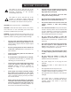
CARACTERÍSTICAS DE PROTECCIÓN El IP™-Six incorpora características de protección derivadas del compromiso de Peavey con la fiabilidad. Estos completos circuitos de protección protejerán su amplificador en el mundo real. Limitación de Saturación Con el amplificador a Potencia total, o punto de saturación, la ganancia de canal se reducirá automáticamente, protegiendo a los altavoces de alta potencia dañina y ondas cuadradas contínuas que podrían ser producidas de otra manera.
IP™-Six ESPECIFICACIONES Potencia estimada a 4 ohmios bridge 825 vatios a 1 kHz <0.025% THD Potencia a 8 ohmios bridge/70 volts 612 vatios a 1 kHz con Onda Senoidal <0.025% THD Potencia de Programa 8 ohms bridge/ 70 volts 800 vatios Potencia estimada a 2 x 2 ohmios 400 vatios por canal a 1 kHz <0.025% THD usando ambos canales Potencia estimada a 2 x 4 ohmios 300 vatios por canal a 1 kHz <0.02% THD usando ambos canales Potencia estimada a 2 x 8 ohmios 180 vatios por canal a 1 kHz <0.
IP™-Six ESPECIFICACIONES Impedancia de Entrada 15k ohmios, balanceada Zumbido y Ruido > -110dB, a una potencia “A” tasada a 4 ohmios Interferencia > -70dB, a una potencia “A” tasada a 4 ohmios Diagrama de Corriente a 1/8 Potencia 465 vatios a 2 ohmios, 320 vatios a 4 ohmios, 210 vatios a 8 ohmios Diagrama de Corriente a 1/3 Potencia 996 vatios a 2 ohmios, 683 vatios a 4 ohmios, 396 vatios a 8 ohmios Diagrama de Potencia en Reposo 30 vatios Diagrama de Potencia Máxima 1752 vatios a 2 ohmios, 115
WARRANTY Architectural Acoustics® PEAVEY ELECTRONICS CORPORATION LIMITED WARRANTY Effective Date: July 1, 1998 What This Warranty Covers Your Peavey Warranty covers defects in material and workmanship in Peavey products purchased and serviced in the U.S.A. and Canada.
Peavey Electronics Corporation • 711 A Street • Meridian, MS 39301 601-483-5376 • Fax 601-486-1678 • http://aa.peavey.