
User manual


8
IP
™
-Six Power Amplifier
Congratulations on your purchase of a Peavey Architectural Acoustics IP-Six power amplifier. Please
read this manual carefully (especially the “Important Precautions” section located inside the front
cover) as it contains information vital to the safe operation of the amplifier. Also, please fill out and
return the enclosed product registration card.
IP-Six amplifiers are ruggedly built from high quality components and feature comprehensive
protection circuits to protect your amplifier in the real world.
If you need setup or operation assistance for this product, please call Architectural Acoustics
Customer Service Tech Service or your local authorized dealer. We appreciate suggestions that may
help us improve our products or service.
Unpacking
Inspect the amplifier during unpacking. If you find any damage, notify your dealer immediately. Only
the consignee may institute a claim with the carrier for damage incurred during shipping. Be sure
to save the carton and all packing materials. Should you ever need to ship the unit back to Peavey
Electronics, one of its service centers or the dealer, use only the original factory packaging.
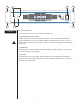
Mounting
IP-Six amplifiers are two rack space units of 13.5" (343 mm) depth that mount in a standard 19" rack.
On all amplifiers, four front-panel mounting holes are provided. Rear-mounting ears are also provided
on all amplifiers for additional support. Distance from the back of the front-rack ear to the center of
the rear-mounting ear holes is 13 1/8" (333 mm).
To set the amplifier up for basic usage:
1. Rack mount the amplifier in the location where it is to be used, remembering to allow for
adequate access and cooling space. For more information, see the sections on Installation,
Mounting and Cooling Requirements.
2. Make input connections to the plugable terminal blocks on the input module. Use the
proper connections for stereo, parallel, bridged mono and grounding configuration. See the
sections on Signal Mode Configuration and Input Module Connections for more information.
3. Connect speakers to the output barrier strip. Be sure to make the correct output
connections for stereo, parallel or bridged mono configuration. See the section on Speaker
Output Connections for more information.
4. Make power connections, allowing for proper current draw. See the section on AC Mains
Circuit Size Requirements for more information.
5. Turn the front panel AC switch to ON, and bring up the back-panel gain attenuators to the
desired levels.
ENGLISH
Introduction
Installation and
Mounting