
User manual


9
POWER
I N D U S T R I A L P O W E R A M P L I F I E R
CLIP
STATUS
Ch A Ch B
- S I X
by
TM
RCHITECTURAL
COUSTICS
ON
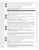
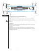
Front Panel
(1) Rack Mounting Ears
Two mounting holes are provided on each front mounting ear.
(2) AC Power Switch/Circuit Breaker
A power switch-and-circuit breaker combination switch is on the front panel. With the switch
pushed toward the up position, the amplifier is ON. If the switch/breaker continues to trip, the
amplifier needs servicing. Do not continue to reset, as severe internal damage and safety hazards
could occur!
(3) STATUS LED
Each channel has a Status LED which indicates that the corresponding channel is active and has
its speaker protection relays engaged.
(4) CLIP LED
Each channel has a Clip Limiting LED. This LED illuminates at the clipping point and indicates
that internal circuitry is reducing amplifier gain to allow full power. See the section on Protection
Features for more information.
1
1
1
1
2
4
3