
Service manual


118
KC297
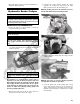
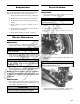
8. Remove the lower shock absorber eyelet from the
upper A-arm.
9. Remove the cap screws securing the A-arms to the
frame.
10. Remove the circlip from the ball joint; then remove
the ball joint from the A-arm.
CLEANING AND INSPECTING
1. Clean all A-arm components using a pressure
washer.
2. Clean the ball joint mounting hole of all residual
Loctite, grease, oil, or dirt for installing purposes.
3. Inspect the A-arm for bends, cracks, and worn bush-
ings.
4. Inspect the ball joint mounting holes for cracks or
damage.
5. Inspect the frame mounts for signs of damage, wear,
or weldment damage.
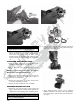
INSTALLING
1. Apply green Loctite #609 to the entire outside diam-
eter of the ball joint; then install the ball joint into the
A-arm and secure with the circlip.
2. Install the A-arm assemblies into the frame mounts
and secure with the cap screws. Only finger-tighten
at this time.
3. Secure the lower eyelet of the shock absorber to the
upper A-arm. Tighten nut to 35 ft-lb.
4. Secure the A-arm assemblies to the frame mounts
(from step 2). Tighten the cap screws to 35 ft-lb.
5. Install the knuckle assembly onto the ball joints and
secure with cap screws. Tighten to 35 ft-lb.
6. Apply grease to the hub and drive axle splines; then
install the hub assembly onto the drive axle.
7. Secure the hub assembly with the nut. Tighten only
until snug.
8. Secure the brake caliper to the knuckle with the two
“patch-lock” cap screws. Tighten to 20 ft-lb.
9. Secure the hub nut (from step 7) to the shaft/axle.
Tighten to 200 ft-lb.
10. Install a new cotter pin and spread the pin to secure
the nut.
11. Install the wheel and tighten to 40 ft-lb (steel) or 80
ft-lb (aluminum).
12. Remove the ATV from the support stand.
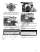
Rear A-Arms
REMOVING
1. Secure the ATV on a support stand to elevate the
wheels
.
2. Pump up the hand brake; then engage the brake lever
lock.
3. Remove the wheel.
4. Remove the cotter pin securing the hex nut; then
remove the hex nut. Release the brake lever lock.
5. Remove the caliper (right side only).
NOTE: Do not allow the brake caliper to hang from
the hose.
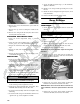
6. Remove the cap screws and lock nut securing the
shock absorber to the frame and lower A-arm; then
remove the shock absorber.
KC0100
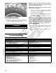
7. Slide the hub out of the knuckle and set aside.
8. Remove the cap screws and lock nuts securing the
knuckle to the A-arms. Discard the lock nuts.
NOTE: Never reuse a lock nut. Once a lock nut has
been removed, it must be replaced with a new lock
nut.
9. Remove the cap screws and lock nuts securing the
A-arms to the frame; then remove the A-arms.
CAUTION
Do not tighten the nut beyond the 35 ft-lb specification
or the shock eyelet or mount WILL be damaged.
! WARNING
Make sure the ATV is solidly supported on the support
stand to avoid injur y.