
Service manual

42
CC136D
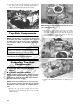
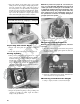
NOTE: The valve seals must be replaced.
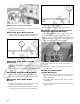
3. Remove the valve springs; then invert the cylinder
head and remove the valves.
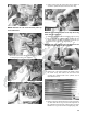
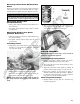
Measuring Valve Stem Runout
1. Support each valve stem end with the V Blocks; then
check the valve stem runout using a dial indicator.
ATV-1082
2. Maximum runout must not exceed specifications.
Measuring Valve Stem Outside
Diameter
1. Using a micrometer, measure the valve stem outside
diameter.
2. Acceptable diameter ranges must be within specifi-
cations.
Measuring Valve Face/Seat Width
1. Using a calipers, measure the width of the valve face.
2. Acceptable width must be at or above specifications.
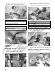
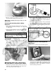
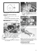
Measuring Valve Face Radial
Runout
1. Mount a dial indicator on the surface plate; then
place the valve stem on a set of V blocks.
2. Position the dial indicator contact point on the out-
side edge of the valve face; then zero the indicator.
ATV1082A
3. Rotate the valve in the V blocks.
4. Maximum runout must not exceed specifications.
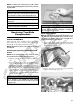
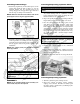
Measuring Valve Guide/Valve Stem
Deflection (Wobble Method)
1. Mount a dial indicator and base on the surface plate;
then place the cylinder head on the surface plate.
2. Install the valve into the cylinder head; then position
the dial indicator contact point against the outside
edge of the valve face. Zero the indicator.
CC131D
3. Push the valve from side to side; then from top to
bottom.
4. Maximum “wobble” deflection must not exceed
specifications.
Measuring Valve Guide
(Inside Diameter)
1. Insert a snap gauge 1/2 way down into each valve
guide bore; then remove the gauge and measure it
with a micrometer.
2. Acceptable inside diameter range must be within
specifications.
3. If a valve guide is out of tolerance, the cylinder head
must be replaced.