
Service manual

93
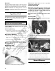
2. With appropriate needle adapters on the meter leads,
connect the red tester lead to the voltage lead (V);
then connect the black tester lead to the ground lead
(G).
KC248A
3. Turn the ignition switch to the ON position.
4. The meter must show greater than 5.0 volts.
5. Leave the black tester lead connected; then connect
the red tester lead to the signal lead pin (S).
6. Slowly move the ATV forward or backward; the
meter must show 0 and 6 volts alternately.
NOTE: If the sensor tests are within specifications,
the speedometer must be replaced (see Steer-
ing/Frame/Controls - LCD Gauge).
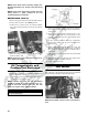
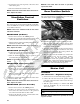
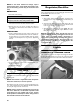
To replace a speed sensor, use the following procedure.
1. Disconnect the three-wire connector from the speed
sensor; then remove the cap screw securing the sen-
sor to the sensor housing.
2. Remove the sensor from the sensor housing account-
ing for an O-ring.
3. Install the new speed sensor into the housing with
new O-ring lightly coated with multi-purpose grease;
then secure the sensor with the cap screw (threads
coated with blue Loctite #242). Tighten securely.
CD071
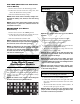
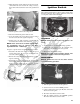
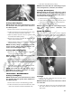
Ignition Switch
The ignition switch harness connects to the switch with a
three-pin connector. To access the connector, remove the
access panel in front of the handlebar.
KC339D
VOLTAGE
NOTE: Perform this test on the main harness con-
nector.
1. Set the meter selector to the DC Voltage position.
2. Connect the red meter lead to the red/white wire;
then connect the black meter lead to ground.
3. Meter must show battery voltage.
NOTE: If the meter shows no battery voltage, trou-
bleshoot the battery or the main wiring harness.
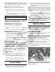
RESISTANCE
NOTE: Perform this test on the switch harness
using the following procedure.
KC276A
1. Turn the ignition switch to the ON position.
2. Set the meter selector to the OHMS position.
3. Connect either tester lead to pin B; then connect the
other tester lead to pin A.
4. The meter must show less than 1 ohm.
5. Turn the ignition switch to the LIGHTS position.
The meter must show less than 1 ohm.