KAP08R1AWT KAP10R1AWT
3 23 24 25 26 31 33
Safety Precautions Safety Safety Precautions Read Safety Precautions Before Operation and Installation To prevent death or injury to the user or other people and property damage, the following instructions must be followed. Incorrect operation due to ignoring of instructions may cause death, harm or damage. WARNING This symbol indicates the possibility of personnel injury or loss of life. CAUTION This symbol indicates the possibility of property damage or serious consequences.
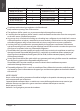
Safety Precautions • In a thunderstorm, the power must be cut off to avoid damage to the machine due to lightning. • Your air conditioner should be used in such a way that it is protected from moisture. e.g. condensation, splashed water, etc. Do not place or store your air conditioner where it can fall or be pulled into water or any other liquid. Unplug immediately if it occurs. • All wiring must be performed strictly in accordance with the wiring diagram located inside of the unit.
• • • • in the presence of inflammable substances or vapour such as alcohol, insecticides, petrol,etc. Always transport your air conditioner in a vertical position and stand on a stable, level surface during use. Always contact a qualified person to carry out repairs. If the damaged power supply cord must be replaced with a new power supply cord obtained from the product manufacturer and not repaired. Hold the plug by the head of the power plug when taking it out. Turn off the product when not in use.
Safety Precautions For R290 amount of refrigerant (kg) Min. room area(m²) amount of refrigerant (kg) Min. room area(m²) <0.0836 and≥ 0.1045 <0.2090 and≥ 0.2299 4 11 <0.1045 and≥ 0.1254 <0.2299 and≥ 0.2508 4 12 <0.1254 and≥ 0.1520 <0.2508 and≥ 0.2717 4 13 <0.1520 and≥ 0.1672 <0.2717 and≥ 0.2926 8 14 <0.1672 and≥ 0.1881 <0.2926 and≥ 0.3040 9 15 <0.1881 and≥ 0.2090 10 Compliance with national gas regulations shall be observed. Keep ventilation openings clear of obstruction.
Safety Precautions Caution: Risk of fire/ flammable materials (Required for R32/R290 units only) Explanation of symbols displayed on the unit(For the unit adopts R32/R290 Refrigerant only): This symbol shows that this appliance used a flammable refrigerant. If the refrigerant WARNING is leaked and exposed to an external ignition source, there is a risk of fire. CAUTION This symbol shows that the operation manual should be read carefully.
Safety Precautions The area shall be checked with an appropriate refrigerant detector prior to and during work, to ensure the technician is aware of potentially flammable atmospheres. Ensure that the leak detection equipment being used is suitable for use with flammable refrigerants, i.e. non-sparking, adequately sealed or intrinsically safe.
Page 9 Safety Precautions being worked upon prior to any removal of sealed covers, etc. If it is absolutely necessary to have an electrical supply to equipment during servicing, then a permanently operating form of leak detection shall be located at the most critical point to warn of a potentially hazardous situation.
Safety Precautions oxygen shall not be used for this task. Flushing shall be achieved by breaking the vacuum in the system with OFN and continuing to fill until the working pressure is achieved, then venting to atmosphere, and finally pulling down to a vacuum. This process shall be repeated until no refrigerant is within the system. When the final OFN charge is used, the system shall be vented down to atmospheric pressure to enable work to take place.
Installation Instructions Preparation NOTE: All the illustrations in the manual are for explanation purpose only. Your machine may be slightly different. The actual shape shall prevail. The unit can be controlled by the unit control panel alone or with the remote controller. This manual does not include Remote Controller Operations, see the <> packed with the unit for details.
Ambient Temperature Range For Unit Operating MODE Temperature Range MODE Temperature Range Cool 17-35°C (62-95°F) Heat(pump heat mode) 5-30°C (41-86°F) Dry 13-35°C (55-95°F) Heat(electrical heat mode) ≥ 30°C (86°F) Installation Instructions Exhaust Hose Installation The exhaust hose and adaptor must be installed or removed in accordance with the usage mode. For COOL,HEAT(heat pump type) or AUTO mode must be installed exhaust hose.
Why is the cooling capacity lower on newer models than on older units? Federal regulations require manufacturers to calculate cooling capacity based on a specific test procedure, which was changed just this year. Models manufactured before 2017 were tested under a different procedure and cooling capacity is measured differently than in prior years’models. So, while the BTUs may be lower, the actual cooling capacity of the air conditioners has not changed.
Window Installation Kit Type window installation: Installation Instructions Step One: Preparing the Exhaust Hose assembly Model A Exhaust hose Exhaust hose assembly Unit adaptor Window slider adaptor Model D Exhaust hose assembly Exhaust hose Unit adaptor Page 14 Air exhaust passage Press the exhaust hose(or extended exhaust hose) into the window slider adaptor(or wall exhaust adaptor) and unit adaptor, clamp automatically by elastic buckles of the adaptors.
Step Two: Install the Exhaust hose assembly to the unit Push the Exhaust hose into the airoutlet opening of the unit along the arrow direction. Installation Instructions Step Three: Preparing the Adjustable Window Slider MODEL A Bolt Window slider A 1. Choose the window sliders according the size of your window. Sometimes, it needs to be cut short to meet the window size, please take extra care to cut it properly. Window slider B 2.
Installation NOTE: Once the Exhaust Hose assembly and Adjustable Window Slider are prepared, choose from one of the following two installation methods. Type 1: Hung Window or Sliding Window Installation(For some models) Installation Instructions Foam seal B (Adhesive type-shorter) Foam seal B (Adhesive type-shorter) Or Foam seal A (Adhesive type) Foam seal A (Adhesive type) 1. Cut the adhesive foam seal A and B strips to the proper lengths, and attach them to the window sash and frame as shown.
Or Installation Instructions 5. Insert the window slider adaptor into the hole of the window slider. NOTE: To ensure proper function, DO NOT overextend or bend the hose. Make sure that there is no obstacle around the air outlet of the exhaust hose (in the range of 500mm) in order to the exhaust system works properly. All the illustrations in this manual are for explanation purpose only. Your air conditioner may be slightly different. The actual shape shall prevail.
Operating Instructions Control Panel Features NOTE: The following control panels are for explanation purpose only. The control panel of the unit you purchased may be slightly different according to the models. Your machine may not contain some indicators or buttons. The actual shape shall prevail. Operating Instructions Auto Heat Wireless MODE button Selects the appropriate operating mode.
Operation Instructions COOL operation · Press the "MODE" button until the "COOL" indicator light comes on. · Press the ADJUST buttons "+" or "-" to select your desired room temperature. The temperature can be set within a range of 17°C~30°C/62°F~88°F(or 86°F). · Press the "FAN SPEED" button to choose the fanspeed. HEAT operation(cooling only models without) · Press the "MODE" button until the "HEAT" indicator light comes on. · Press the ADJUST buttons "+" or " - " to select your desired room temperature.
Operating Instructions thermostat allowing for the precise temperature end of the hose directly over the drain area in your control at its location. To activate the Follow Me/Temp basement floor. Continuous drain hose Sensing feature, point the remote control towards the unit and press the Follow Me/Temp Sensing button. Remove the drain plug The remote control will send this signal to the air conditioner until press the Follow Me/Temp Sensing button again.
Maintenance Safety Precautions · · · · Always unplug the unit before cleaning or servicing. DO NOT use flammable liquids or chemicals to clean the unit. DO NOT wash the unit under running water. Doing so causes electrical danger. DO NOT operate the machine if the power supply was damaged during cleaning. A damaged power cord must be replaced with a new cord from the manufacturer.
Troubleshooting Tips Problem Unit does not turn on when pressing ON/OFF button Possible Causes Solution P1 Error Code The Water Collection Tray is full. Turn off the unit, drain the water from the Water Collection Tray and restart the unit. In COOL mode: room temperature is lower than the set temperature Reset the temperature Contact the manufacturer or its service agents or a similar qualified person for service.
Remote Control Instructions Using The Remote Control Location of the remote controller Use the remote controller within a distance of 8 meters / 26 feet from the appliance, pointing it towards the receiver. Reception is confirmed by a beep. CAUTION • The air conditioner will not operate if curtains, doors or other materials block the signals from the remote controller to the indoor unit. • Prevent any liquid from falling into the remote controller.
Function Buttons Before you begin using your new air conditioner, make sure to familiarize yourself with its remote control. The following is a brief introduction to the remote control itself. For instructions on how to operate your air conditioner, refer to the Operating Instructions section of this manual. SHORT CUT Sets and activates your favorite pre-settings. ON/OFF Turns the unit on or off.
Handling the Remote Control NOT SURE WHAT A FUNCTION DOES? Refer to the Operating Instructions section of this manual for a detailed description of how to use your air conditioner. SPECIAL NOTE Button designs on your unit may differ slightly from the example shown. If the unit does not have a particular function, pressing that function’s button on the remote control will have no effect.
Remote LED Screen Indicators Transmission Indicator Lights up when remote sends signal to unit MODE display Displays the current mode, including: ON/OFF display Appears when the unit is turned on and disappears when it is turned off AUTO COOL DRY HEAT FAN TIMER ON display Displays when TIMER ON is set TIMER OFF display Displays when TIMER OFF is set ECO display Not available on this unit Battery display Low battery detection SLEEP display Displays when SLEEP function is activated FOLLOW ME display Indic
Basic Fuctions SETTING THE DESIRED TEMPERATURE The operating temperature range for this unit is 17-30°C (62°F-86°F). You can increase or decrease the set temperature in 1°C (1°F) increments. 3 1 2 AUTO operation O N /O F F SHORT CUT MODE TIMER ON In AUTO mode, the unit will automatically select the COOL, FAN, HEAT or DRY mode based on the set temperature. TIMER OFF 1. Press the MODE button to select Auto mode. T E MP FAN FOLLOW ME SLEEP 2.
Basic Fuctions (cont.) FAN operation 1. Press the MODE button to select FAN mode. 2. Press FAN button to select the fan speed: AUTO, LOW, MED or HIGH. 3. Press the ON/OFF button to start the unit. 3 O N /O F F 1 MODE 2 FAN SHORT CUT TIMER ON NOTE T E MP TIMER OFF FOLLOW ME SLEEP You cannot set temperature in FAN mode. As a result, your remote control’s LCD screen will not display temperature. LED HEAT operation 1. Press the MODE button to select HEAT mode. 2.
Timer Fuctions 1 2 TIMER ON x5 TIMER ON Your air conditioning unit has two timer-related functions: TIMER ON - sets the amount of time after which the unit will automatically turn on. TIMER OFF - sets the amount of time after which the unit will automatically turn off. TIMER ON function 3 1sec 4 2sec The TIMER ON function allows you to set a period of time after which the unit will automatically turn on, such as when you come home from work. 1. Press the TIMER ON button.
Timer Fuctions (cont.) 3. Wait 2 seconds, then the TIMER OFF function will be activated. The digital display on your remote control will then return to the temperature display. T imer on O N /O F F NOTE TIMER ON MODE T E MP TIMER OFF FAN SLEEP FOLLOW ME LED 1 When setting the TIMER ON or TIMER OFF functions, up to 10 hours, the time will increase in 30 minute increments with each press. After 10 hours and up to 24, it will increase in 1 hour increments.
Advanced Fuctions SLEEP Function The SLEEP function is used to decrease energy use while you sleep (and don’t need the same temperature settings to stay comfortable). This function can only be activated via remote control. Note: The SLEEP function is not available in FAN or DRY mode. O N /O F F SHORT CUT TIMER ON MODE T E MP TIMER OFF FAN SLEEP FOLLOW ME LED FOLLOW ME Function 1. Press FOLLOW ME button to activate function.
NOTE This equipament has been tested and found to comply with the limits for Class B digital device, pursuant to Part 15 of the FCC Rules. These limits are designed to provide reasonable protection against harmful interference in a residential installation. This equipament generates, uses and can radiate radio frequency energy and, if not installed and used in accordance with the instructions, may cause harmful interference to radio communications.
Warranty Air Conditioner Limited Warranty Your product is protected by this Limited Warranty: Warranty service must be obtained from Midea Consumer Services or an authorized Midea servicer. Warranty • One year full warranty from original purchase date. Midea, through its authorized servicers will: • Pay all costs for reparing or replacing parts of this appliance which prove to be defective in materials or workmanship.
The design and specifications are subject to change without prior notice for product improvement. Consult with the sales agency or manufacturer for details. Any updates to the manual will be uploaded to the service website, please check for the latest version.