
User's Manual


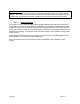

Table Of Contents
- Hub Installation Checklist – 6x60-degree
- Link Budget Parameters for 6x60 Hub
- Wireless Cable Modem Configuration – CXC150W
- W-CMTS BSR1000W Setup Guide
- Factory Settings BSR1000W
- Connecting to the BSR1000 CMTS
- Setting the System Passwords
- Configure the Ethernet IP Address
- Configure Cable IP Address
- Configure the CMTS
- Configure Downstream Port
- Configure Upstream Ports:
- Configure Basic Routing
- Save the Configuration
- Creating a static route from the server to the BSR1000
- Windows 2000 DHCP Server
- Time-of-Day Server Setup Guide
- BSR1000W SNMPc View and Community
- SolarWinds’ TFTP-Server
- Cable System Basics
- Reader Feedback

Table 5-1 – Lightning Protector Part Numbers
Ref # Item Part #
1 75 ohm RG-6 transmit and receive cable IS-75F-C1
2 DC Power Supply IS-17VDC-30A-NG
The ground bus, in turn, should be connected with an appropriate conductor (minimum #6
AWG) to the hub site ground that includes the power service and building common ground, per
the NEC and local codes.
Arcwave recommends the installer run a minimum #6 AWG conductor between the equipment
room ground bus and a common ground point adjacent to the Hub Transceiver(s) unless the
transceiver mounting system consists of a known low impedance ground (as a steel tower or
monopole). In the case of a single sector Hub Transceiver installation, this point can be the
antenna ground bolt or mounting bracket. In a multi sector installation including an outdoor
junction box (OJB) this conductor can be connected to the ground bus in the OJB, which in turn,
is connected to each transceiver and any nearby building or support structure ground.
Normally the Wireless CMTS (W-CMTS), upconverter(s), DC power supply, 100baseT data
switch, etc. are mounted in a 19-inch equipment rack in the base station equipment room. This
rack should also be connected to the ground bus, preferably by a conductor #6 AWG or greater.
When shielded cable is utilized to connect DC power between the hub equipment room and the
hub antenna, ground the shield to the ground bus in the equipment room.
Figures 5-10 and detail 5-11 show a ground bus installation with the specified PolyPhaser
protector on each IF cable and on the antenna lead for a backhaul microwave. Note the ground
strap to the right, which connects to the equipment rack.
Lighting Protector
for Backhaul
Microwave
Antenna Cable
Ground strap to rack
Ground wire from buildingGround bus bar
Cable-Building entrance
Figure 5-10: Example of Hub protection at building entrance.
June 2003 Page 5-10